Installation – Xylem IM167 R8 Aquavar CPC (Centrifugal Pump Control) User Manual
Page 30
30
X1
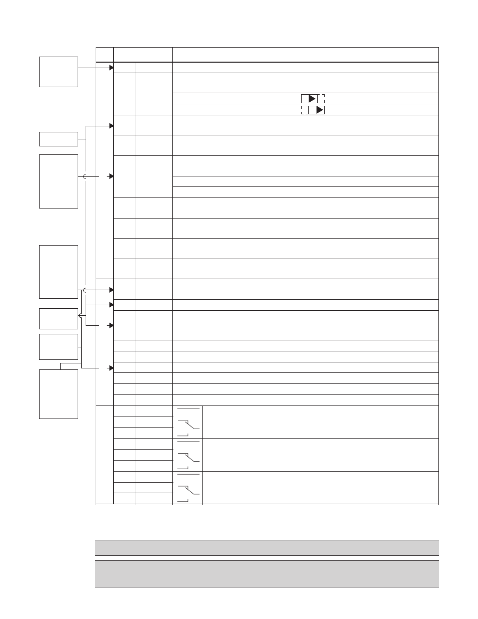
Control Wiring
1
SCR
Terminal for transducer shield. (Connected internally to chassis ground.)
Analog input channel 1, 2nd transducer. Default
2
= frequency reference.
2
AI1
Resolution 0.1%, accuracy ±1%.
J1:AI1 OFF: 0…10 V (Ri = 312 kΩ)
J1:AI1 ON: 0…20 mA (Ri = 100 Ω)
Switch positions listed on page 25.
3
AGND
Analog input circuit common. (Connected internally to chassis gnd.
through 1 MW. Jumper wire to X1-11.)
4
+10 V
10 V/10 mA reference voltage output for analog input potentiometer,
accuracy ±2%. (Not used.)
Analog input channel 2.
5
AI2
Resolution 0.1%, accuracy ±1%.
Transducer input
4–20 mA
6
AGND
Analog input circuit common. (Connected internally to chassis gnd.
through 1 MΩ)
7
AO1
Analog output, programmable. Default
2
= Not used. Current 0…20 mA
(load < 500 Ω)
8
AO2
Analog output, programmable. Default
2
= Not used. 0…20 mA
(load < 500 Ω)
9
AGND
Analog output circuit common (Connected internally to chassis gnd.
through 1 MΩ)
10 +24V
Auxiliary voltage output 24 VDC / 250 mA (reference to GND). Short
circuit protected. Transducer/digital input power supply.
11 GND
Auxiliary voltage output common. (Connected internally as floating.)
Digital input common. To activate a digital input, there must be ≥+10 V
12 DCOM
(or ≤-10 V) between that input and DCOM. The 24 V may be provided by
the AQUAVAR (X1-10) or by an external 12…24 V source of either polarity.
13 DI1
Digital input 1, programmable. Default
2
= run enable (Group 24)
14 DI2
Digital input 2, programmable. Default
2
= low water (Group 24)
15 DI3
Digital input 3, programmable. Default
2
= E-stop or jumper
16 DI4
Digital input 4, programmable. Default
2
= set point selection
17 DI5
Digital input 5, programmable. Default
2
= HOA (Group 12)
18 DI6
Digital input 6, programmable. Default
2
= not used
19 RO1C
Relay output 1, programmable. Default
2
= drive ready
20 RO1A
Maximum: 250 VAC / 30 VDC, 2 A
21 RO1B
Minimum: 500 mW (12 V, 10 mA)
22 RO2C
Relay output 2, programmable. Default
2
= pump run
23 RO2A
Maximum: 250 VAC / 30 VDC, 2 A
24 RO2B
Minimum: 500 mW (12 V, 10 mA)
25 RO3C
Relay output 3, programmable. Default
2
= fault
26 RO3A
Maximum: 250 VAC / 30 VDC, 2 A
27 RO3B
Minimum: 500 mW (12 V, 10 mA)
1
Digital input impedance 1.5 kΩ. Maximum voltage for digital inputs is 30 V.
2
Default values depend on the macro used. Values specified are for the default macro, single/multipump.
NOTE: Jumper Wires between 3 and 11, 10 and 15, 11 and 12.
NOTE! Terminals 3, 6 and 9 are at the same potential.
NOTE! For safety reasons the fault relay signals a “fault” when the AQUAVAR is
powered down.
INSTALLATION
(All Frames)
ON
ON
R
elay Outputs
Transducer
Screen/
Shield
(–)
Transducer
(4-20mA)
Connection
(White
or Black)
(+)
Transducer
Power
Supply
(Brown
or Red)
Analog I/O
Digital Inputs
1
E-stop/
start Jump
to +24V for
enable
(15 to 10
Jumper)
10 – 15
E-stop
or Jumper
Jumper Wire
Jumper Wire
11 and 12