Relay outputs, Analog i/o, Digital inputs – Xylem IM167 R8 Aquavar CPC (Centrifugal Pump Control) User Manual
Page 3
3
Wiring
the T
ransducer
1.
R
oute the
tr
ansducer
cable
thr
ough
the conduit.
2.
S
trip the
tr
ansducer
cable
she
athing
and twist
the scr
een
wir
e.
3.
C
onnect the scr
een
wir
e of
the
tr
ansducer to
terminal X1-1.
4.
C
onnect the power supply wir
e of
the
tr
ansducer (r
ed or br
own) to terminal
X1-10.
5.
C
onnect analog output wir
e fr
om the
tr
ansducer (white or black) to
X1-5.
See char
t in ne
xt column.
Note 1.
Jumper Set
ting: (Analog Input)
J1
AI1:
0…10 V
AI2: 0(4)…20 mA
(default)
Relay output 1,
pr
o-
19
RO1C
gr
ammable.
Default
2
= run power to drive
20
RO1A
Maximum:
250 V
A
C/
30
VDC,
2
A
21
RO1B
Minimum: 500 mW
(12
V,
10 mA)
Relay output 2, pro-
22
RO2C
grammable. Default
2
= r
eady
, pump is
running
23
RO2A
Maximum:
250 V
A
C/
30
VDC,
2
A
24
RO2B
Minimum: 500 mW
(12
V,
10 mA)
Relay output 3,
pr
o-
25
RO3C
gr
ammable.
Default
2
= not used
26
RO3A
Maximum:
250 V
A
C/
30
VDC,
2
A
27
RO3B
Minimum: 500 mW
(12
V,
10 mA)
6.
Install the conduit/gland bo
x cover (1
scr
ew).
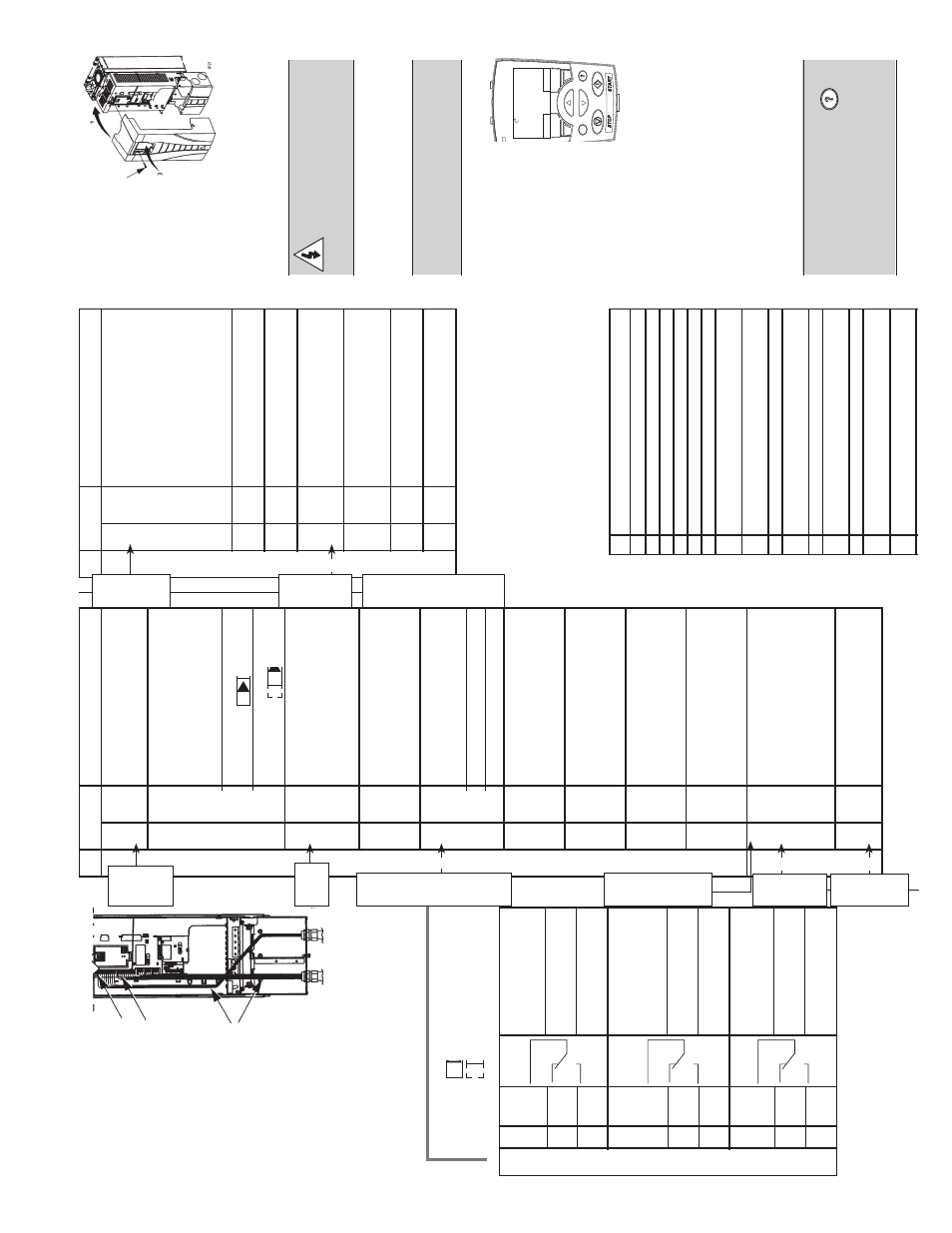
X1
C
ontr
ol Wiring
Digital input common.
To activa
te a digital input,
ther
e must be
≥
+10V
(or
≤
-10V) between tha
t
12
DC
OM
input and DC
OM.
T
he 24V
may be pr
ovided by the
A
QU
A
VAR (X1-10) or by
an e
xternal 12…24V
sour
ce of
either polarity
.
13
DI1
Digital input 1,
selectable.
Default
2
= run enable
14
DI2
Digital input 2,
selectable.
Default
2
= low wa
ter
Digital input 3,
15
DI3
selectable.
Default
2
= E-stop or jumper
Digital input 4,
16
DI4
selectable.
Default
2
= set point selection
17
DI5
Digital input 5,
selectable.
Default
2
= not used
18
DI6
Digital input 6,
selectable.
Default
2
= not used
1
Digital input impedance 1.5 k
Ω
. Maximum voltage
for digital inputs is 30
V.
2
Default values depend on the macr
o used.
V
alues
specified ar
e for the default macr
o
, single/multi-
pump
.
NO
TE:
Jumper
Wir
es between 3 and 11,
10 and 15,
11 and 12.
Check Installa
tion
Befor
e applying power
, perform the follow
-
ing check
s.
√
Check
Envir
onment conforms to specifica
tions.
The drive is mounted secur
ely
.
Pr
oper cooling space ar
ound the drive.
Motor and driven equipment ar
e r
eady for star
t.
Floa
ting network
s: Internal RFI filter disconnected.
Drive is pr
operly gr
ounded,
with pump/motor
.
Input power (mains) voltage ma
tches the drive
nominal input voltage.
The input power (mains) terminals,
U1,
V1,
W1,
ar
e connected and tightened as specified.
The input power (mains) fuses / mains switch installed.
The motor terminals,
U2,
V2,
W2,
ar
e connected
and tightened as specified.
Motor cable is r
outed away fr
om other cables.
NO power factor compensa
tion capacitors ar
e
connected to the motor cable.
Contr
ol terminals ar
e wir
ed and tightened as specified.
NO tools or for
eign objects (such as drill shavings) ar
e
inside the drive.
NO alterna
te power sour
ce for the motor is connected
– no input voltage is applied to the output of
the drive.
R
einstall the C
over
1.
Align the cover
and slide
it on.
2.
T
ighten
the
captive scr
ew
.
3.
R
einstall the
contr
ol panel.
Apply P
ower
Always r
einstall the fr
ont cover befor
e
turning power on.
W
ARNING!
T
he
A
QU
A
VAR
will star
t up automa
tically a
t
power up
, if
the e
xternal run
command is on.
1.
Apply input power
.
When power is applied to the
A
Q-
U
A
VAR,
the gr
een LED comes on.
NO
TE!
Befor
e incr
easing motor
speed,
check tha
t the motor is run-
ning in the desir
ed dir
ection.
Star
t-Up
In S
tar
t-Up
, enter motor
da
ta (collected e
arlier)
and,
if
needed,
edit pa
-
rameters tha
t define how
the drive oper
ates and
communica
tes.
Wizar
ds
The S
tar
t-Up
Wizar
d steps thr
ough
typical star
t-up selections and runs
automa
tically upon the initial power
up
. At other times,
use the steps
below to run the S
tar
t-Up
Wizar
d.
1.
Use the MENU k
ey to access the
Menu list.
2.
Select Wizar
ds.
3.
Select S
tar
t-Up
Wizar
ds.
4.
F
ollow the scr
een instructions to
configur
e the system.
DEF
A
UL
T P
ASSW
ORD IS “66”
.
NO
TE!
F
or common par
ameters and
menu items,
use the Help K
ey to
display descriptions.
If
you encounter
Alarms or F
aults,
use the Help K
ey or
refer to the Diagnostic section of
the
instruction manual.
5
3
1
ON
ON
DIR
MENU
REM
11.1%
LO
C
REM
40.2 PSI
sp
0.0 PSI
ac
0.0 HZ
Relay Outputs
10–15 E-stop
or
Jump
-
er
Jumper
Wir
e
ON
ON
X1
C
ontr
ol Wiring
Terminal for tr
ansducer
1
SCR
shield.
(C
onnected inter
-
nally to chassis gr
ound.)
Analog input channel 1,
2nd tr
ansducer
. Default
2
= fr
equency r
efer
ence.
Resolution 0.1%,
2
AI1
accur
acy ±1%.
J1:AI1 OFF
: 0…10
V
(Ri =
312 k
Ω
)
J1:AI1 ON: 0…20 mA
(Ri
= 100
Ω
)
Analog input cir
cuit com-
mon.
(C
onnected inter
-
3
AGND
nally to chassis gnd.
thr
ough 1 MW
. Jumper
wir
e
to X1-11.)
10
V/10 mA
refer
ence
4
+10V
voltage output for analog
input potentiometer
,
accur
acy ±2%.
(Not used.)
Analog input channel 2.
Resolution 0.1%,
5
AI2
accur
acy ±1%.
Tr
ansducer input
4–20 mA
Analog input cir
cuit com-
6
AGND
mon.
(C
onnected inter
-
nally to chassis gnd.
thr
ough 1 M
Ω
)
Analog output,
pr
ogr
am-
7
AO
1
mable.
Default
2
= Not
used.
Curr
ent 0…20 mA
(load < 500
Ω
)
Analog output,
pr
ogr
am-
8
AO
2
mable.
Default
2
= Not
used.
0…20 mA
(load < 500
Ω
)
Analog output cir
cuit
9
AGND
common (C
onnected
internally to chassis gnd.
thr
ough 1 M
Ω
)
Auxiliary voltage output
24
VDC / 250 mA
10
+24V
(r
efer
ence to GND).
Shor
t cir
cuit pr
otected.
Tr
ansducer/digital input
power supply
.
Auxiliary voltage output
11
GND
common.
(C
onnected
internally as floa
ting.)
Tr
ans-
ducer
Scr
een/
Shield
(–)
Tr
ans-
ducer
(4 -20
mA)
Conn-
ection
(White
or
Black)
Analog I/O
(–)
Trans-
ducer
Power
Supply
(Br
own
or R
ed)
Jump
-
er
Wir
e
11
and
12
Digital Inputs
1
10–15 E-stop
or
Jump
-
er
Jump
-
er
Wir
e
11
and
12
E-stop
/star
t
Jump
to
+24V
for en
-
able
(15
to 10
Jump
-
er)
Digital Inputs
1