Features – Xylem IM167 R8 Aquavar CPC (Centrifugal Pump Control) User Manual
Page 107
107
Pump Protect Ctrl
This feature is designed to protect the pump from lack of available NPSH, loss of or low
suction, pump run-out. This pump protection feature is exclusive to the Aquavar
®
and
measures the discharge pressure of the pump via the transducer, and compares it with the
minimum allowed system pressure as entered into parameter (2403) PROTECTION LIMIT. If
this parameter is set, then a time delay will need to be set in number of seconds allowed to
run at or below this limit, before shutting down on a fault.
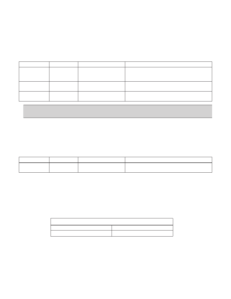
Parameter
Name
Value/Range
Note(s)
24.02
PUMP
Disabled (Default)
Provides no warning, warning or
PROTECT
WARN
warning and then shut off.
CTRL
WARN & CTRL.
24.03
PROTECTION 0 – 6553.5
Actual value units.
LIMIT
24.04
PROTECTION 0 -200 seconds
Provides a time delay for 24.03.
DELAY
NOTE: It is recommended to set this pump protection according to
suggested minimum allowed system requirements. (i.e. pump run-out limits)
Regulation Mode
The regulation mode can either be NORMAL or INVERSE. The default and more common
selection is NORMAL, where the Aquavar software anticipates an increase in system pressure,
and will decrease speed of the pump based on a rising system pressure. If the regulation
mode is set to INVERSE, the process condition is expected to increase with a decrease in
pump speed.
Parameter
Name
Value/Range
Note(s)
21.01
REGULATION NORMAL (Default)
Inverse is normally used for control of
MODE
INVERSE
suction side systems.
EXAMPLE – If an Aquavar unit is trying to control the level in a suction-side tank or sump, the regulation mode
would be set to INVERSE. As the level in the sump increased, Aquavar would respond by increasing pump speed
to maintain a constant level.
Relay Outputs
The AQUAVAR CPC has three relay outputs that are configurable for different operating
and fault conditions. Relays will revert to original states once warnings or faults are reset or
cleared.
Comment(s)
Maximum Contact Voltage
30 VDC, 250 VAC
Maximum Continuous Current
2 A RMS
Refer to the terminal layout diagram for RELAY OUTPUT specifications.
Maximum Contact current/ power = 6A, 30 VDC, 1500 VA, 250 VAC
FEATURES