Aq u ava r, Centrifugal p ump c ontr oller quick start guide – Xylem IM167 R8 Aquavar CPC (Centrifugal Pump Control) User Manual
Page 2
2
A
Q
U
AVA
R
®
CPC
C
entrifugal P
ump C
ontr
oller
Quick Start Guide
Overview
The installa
tion of
the
A
QU
A
VAR CPC adjust-
able speed drive follows the outline below
.
Task
PREP
ARE
for installa
tion
UNP
A
CK
the drive
PREP
ARE
mounting loca
tion
REMO
VE
the fr
ont cover
MOUNT
the drive
INS
TALL
wiring
CHECK
installa
tion
REINS
TALL
the cover
APPL
Y
power
ST
AR
T-UP
Wizar
ds
Applica
tion
This guide pr
ovides a quick r
efer
ence for
installing
Aquavar CPC drives having a stan
-
dar
d enclosur
e (NEMA
1).
NO
TE:
T
his guide does not pr
ovide detailed
installa
tion,
safety or oper
ational instruc
-
tions.
See the Installa
tion Oper
ation Manual
for complete informa
tion.
Pr
epar
e for Installa
tion
W
ARNING!
T
he
Aquavar should ONL
Y
be installed by a qualified electrician.
Check
• Motor C
ompa
tibility – Motor type,
nominal curr
ent,
frequency and voltage r
ange must ma
tch drive
specifica
tions (3 phase motor only).
• Suitable Envir
onment – Drive r
equir
es he
ated,
indoor contr
olled envir
onment tha
t is suitable for
the selected enclosur
e below 104º F
.
• Wiring – F
ollow local codes for wiring and fusing
requir
ements.
R
efer to NEC,
Local,
S
ta
te or Munici
-
pal codes.
Refer to the Installa
tion Oper
ation Manual and
confirm tha
t all pr
epar
ations ar
e complete.
Tools R
equir
ed
Scr
ewdrivers,
wir
e stripper
, tape me
asur
e,
mount
-
ing scr
ews or bolts,
and drill.
Use the following char
t to interpr
et the type code
found on the drive label.
C
ollect Motor Da
ta
C
ollect the following da
ta fr
om the motor namepla
te
pla
te for la
ter use in the
Aquavar star
tup:
•
Voltage
______________________________
• Nominal Motor Curr
ent
_______________
• Nominal F
requency
___________________
• Nominal Speed
______________________
• Nominal P
ower
_______________________
Unpack the Drive
NO
TE:
Lif
t the
Aquavar by its chassis and
not
by
its cover
.
1.
Unpack the drive.
2.
Check for any damage and notify the
shipper immedia
tely if
damaged com
-
ponents ar
e found.
3.
Check the contents against the or
der
and the shipping label to verify tha
t all
par
ts have been r
eceived.
Pr
epar
e the Mounting L
oca
tion
The drive r
equir
es a smooth,
ver
tical,
solid surface,
fr
ee fr
om
he
at and moistur
e,
with fr
ee
space for air flow – 200 mm (8
in.) above and below
, and 25
mm (1 in.) ar
ound the sides of
the drive.
1.
Mark the mounting
points.
2.
Drill the mounting holes.
R
emove the F
ront C
over
1.
R
emove the contr
ol panel
(display),
if
a
ttached.
2.
L
oosen the
captive scr
ew
at
the top
.
3.
P
ull ne
ar the
top to r
emove
the cover
.
Mount
the Drive
1.
P
osition the
A
QU
A
VAR and use
scr
ews or bolts to
secur
ely tighten all
four corners.
2.
At
tach a warning
stick
er in the
appr
opria
te lan
-
guage on the inside
plastic shell.
Install
the Wiring
(copper only)
1.
Install thin-wall conduit clamps (not supplied) in the conduit/gland bo
x.
2.
Install conduit/gland bo
x.
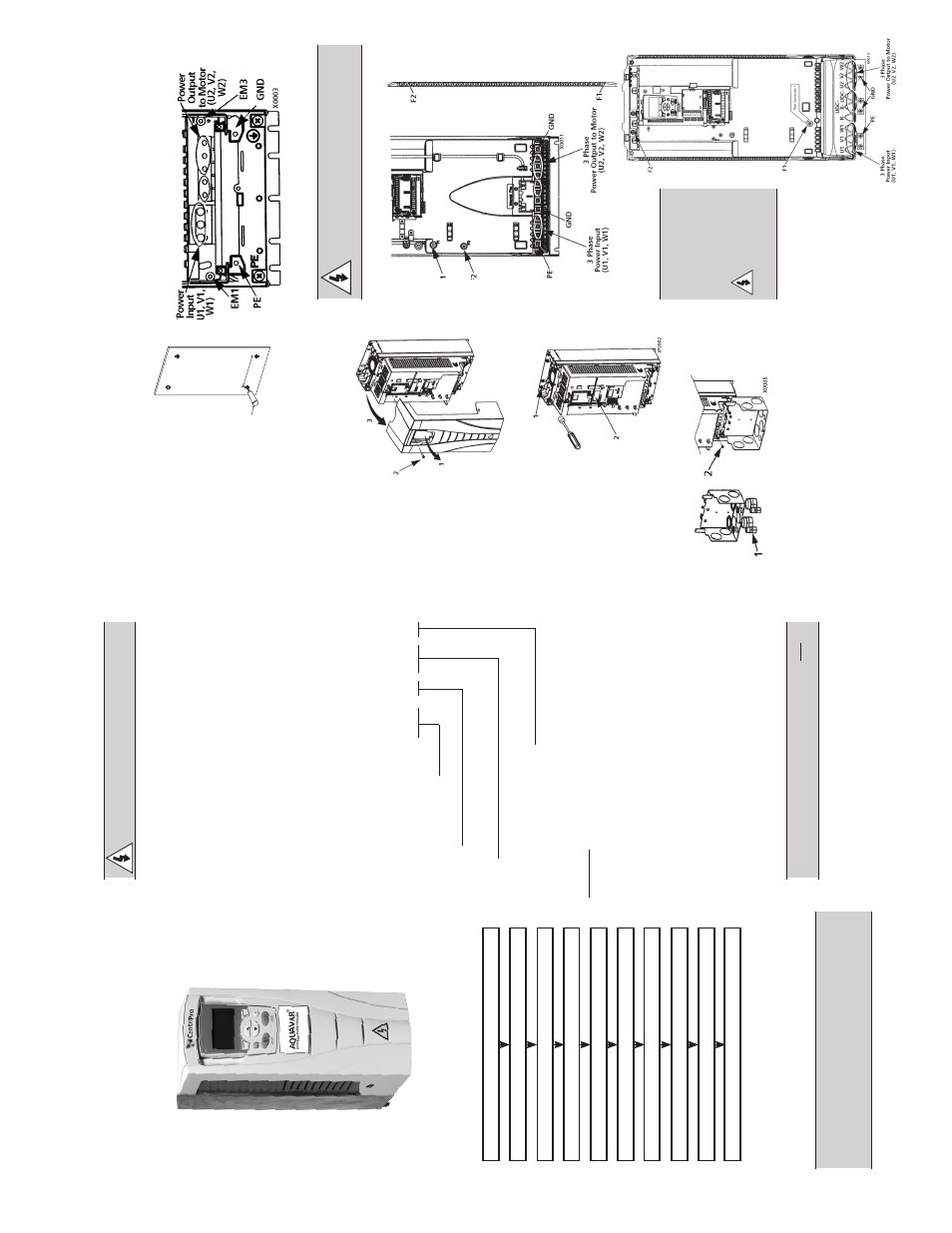
Wiring P
ower
1.
C
onnect conduit runs to bo
x.
2.
R
oute input power and motor
wiring thr
ough conduits.
1
X0002
CPC
4
370
1
A
Q
U
AVA
R
®
(Series)
V
oltage
2 – 230
Volt
4 – 460
Volt
Amps
370 Amps
*See T
echnical
Section
NEMA
Enclosur
e R
ating
1 – NEMA
1
2 – NEMA
12
Options
* C
onsult factory for other options,
if
available.
Not all combina
tions may be available.
3.
S
trip wir
es.
4.
C
onnect power
, motor and
gr
ound wir
es to the drive terminals.
See “P
ower C
onnections”
in the instruction manual.
Fr
ame Sizes R1…R4
* Single phase input power must use U1,
W1
and PE for wiring.
W
ARNING!
F
or floa
ting network
s
remove scr
ews a
t EM1 and EM3 on
Fr
ame Sizes R1…R4.
Fr
ame Size R5
Fr
ame Size R6
W
ARNING!
For floa
ting net
-
work
s r
emove
scr
ews a
t
F1 and F2
on F
rame
Sizes R5 or R6.