Rainbow Electronics AT89C5132 User Manual
Page 85
85
AT8xC5132
4173A–8051–08/02
Table 87. Command Token Format
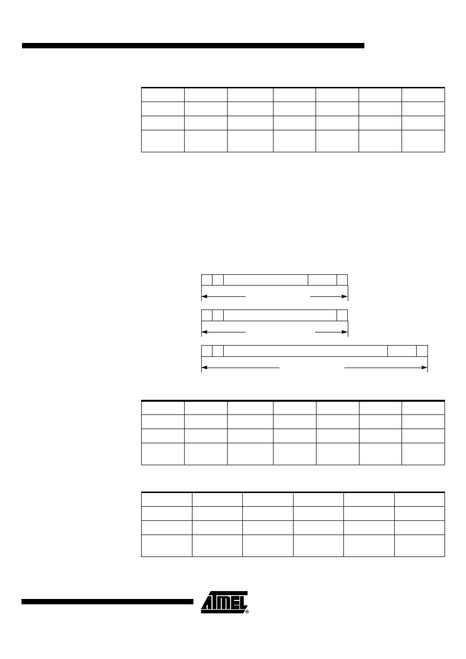
Response Token Format
There are five types of response tokens (R1 to R5). As shown in Figure 58, responses
have a code length of 48 Bits or 136 Bits. A response token is preceded by a Start bit: a
low level on MCMD line and succeeded by an End bit: a high level on MCMD line. The
command content is preceded by a Transmission bit: a low level on MCMD line for a
response token (card to host) and succeeded (R1,R2,R4,R5) or not (R3) by a 7-bit
CRC.
Response content contains mirrored command and status information (R1 response),
CID register or CSD register (R2 response), OCR register (R3 response), or RCA regis-
ter (R4 and R5 response).
Figure 58. Response Token Format
Table 88. R1 Response Format (Normal Response)
Table 89. R2 Response Format (CID and CSD registers)
Bit Position
47
46
45:40
39:8
7:1
0
Width (Bits)
1
1
6
32
7
1
Value
‘0’
‘1’
-
-
-
‘1’
Description
Start bit
Transmission
bit
Command
Index
Argument
CRC7
End bit
Bit Position
47
46
45:40
39:8
7:1
0
Width (Bits)
1
1
6
32
7
1
Value
‘0’
‘0’
-
-
-
‘1’
Description
Start bit
Transmission
bit
Command
Index
Card Status
CRC7
End bit
Bit Position
135
134
[133:128]
[127:1]
0
Width (Bits)
1
1
6
32
1
Value
‘0’
‘0’
‘111111’
-
‘1’
Description
Start bit
Transmission
bit
Reserved
Argument
End bit
0
Total Length = 48 Bits
Content
CRC
0
1
R1, R4, R5
0
Total Length = 136 Bits
Content = CID or CSD
CRC
0
1
R2
0
Total Length = 48 Bits
Content
0
1
R3