Rainbow Electronics AT89C5132 User Manual
Page 52
52
AT8xC5132
4173A–8051–08/02
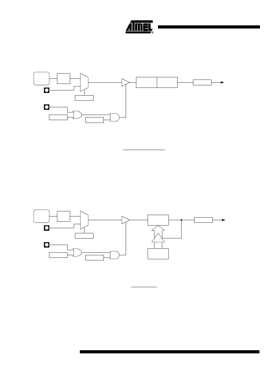
Mode 1 (16-bit Timer)
Mode 1 configures Timer 0 as a 16-bit Timer with TH0 and TL0 registers connected in
cascade (see Figure 30). The selected input increments TL0 register. Figure 31 gives
the overflow period calculation formula when in timer mode.
Figure 30. Timer/Counter x (x = 0 or 1) in Mode 1
Figure 31. Mode 1 Overflow Period Formula
Mode 2 (8-bit Timer with Auto-
Reload)
Mode 2 configures Timer 0 as an 8-bit Timer (TL0 register) that automatically reloads
from TH0 register (see Table 60). TL0 overflow sets TF0 flag in TCON register and
reloads TL0 with the contents of TH0, which is preset by software. When the interrupt
request is serviced, hardware clears TF0. The reload leaves TH0 unchanged. The next
reload value may be changed at any time by writing it to TH0 register. Figure 33 gives
the autoreload period calculation formula when in timer mode.
Figure 32. Timer/Counter x (x = 0 or 1) in Mode 2
Figure 33. Mode 2 Autoreload Period Formula
Mode 3 (Two 8-bit Timers)
Mode 3 configures Timer 0 such that registers TL0 and TH0 operate as separate 8-bit
Timers (see Figure 34). This mode is provided for applications requiring an additional 8-
bit Timer or Counter. TL0 uses the Timer 0 control Bits C/T0# and GATE0 in TMOD reg-
ister, and TR0 and TF0 in TCON register in the normal manner. TH0 is locked into a
Timer function (counting F
T1
/6) and takes over use of the Timer 1 interrupt (TF1) and run
control (TR1) Bits. Thus, operation of Timer 1 is restricted when Timer 0 is in mode 3.
Figure 33 gives the autoreload period calculation formulas for both TF0 and TF1 flags.
TRx
TCON Reg
TFx
TCON Reg
0
1
GATEx
TMOD Reg
Overflow
Timer x
Interrupt
Request
C/Tx#
TMOD Reg
TLx
(8 Bits)
THx
(8 Bits)
INTx#
Tx
TIMx
CLOCK
÷
6
6
⋅
(65536 – (THx, TLx))
TFx
PER
=
F
TIMx
TRx
TCON Reg
TFx
TCON Reg
0
1
GATEx
TMOD Reg
Overflow
Timer x
Interrupt
Request
C/Tx#
TMOD Reg
TLx
(8 Bits)
THx
(8 Bits)
INTx#
Tx
TIMx
CLOCK
÷
6
TFx
PER
=
F
TIMx
6
⋅
(256 – THx)