External interrupts – Rainbow Electronics AT89C5132 User Manual
Page 39
39
AT8xC5132
4173A–8051–08/02
External Interrupts
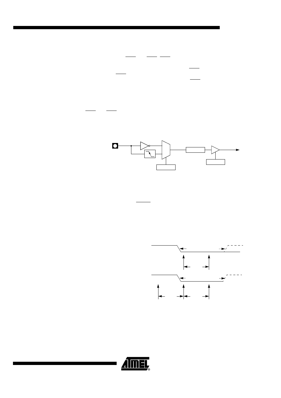
INT1:0# Inputs
External interrupts INT0 and INT1 (INTn, n = 0 or 1) pins may each be programmed to
be level-triggered or edge-triggered, dependent upon Bits IT0 and IT1 (ITn, n = 0 or 1) in
TCON register as shown in Figure 22. If ITn = 0, INTn is triggered by a low level at the
pin. If ITn = 1, INTn is negative-edge triggered. External interrupts are enabled with Bits
EX0 and EX1 (EXn, n = 0 or 1) in IEN0. Events on INTn set the interrupt request flag IEn
in TCON register. If the interrupt is edge-triggered, the request flag is cleared by hard-
ware when vectoring to the interrupt service routine. If the interrupt is level-triggered, the
interrupt service routine must clear the request flag and the interrupt must be deas-
serted before the end of the interrupt service routine.
INT0 and INT1 inputs provide both the capability to exit from Power-down mode on low
level signals as detailed in Section “Exiting Power-down Mode”, page 48.
Figure 22. INT1:0# Input Circuitry
KIN3:0 Inputs
External interrupts KIN0 to KIN3 provide the capability to connect a matrix keyboard. For
detailed information on these inputs, refer to Section “Keyboard Interface”, page 134.
Input Sampling
External interrupt pins (INT1:0 and KIN3:0) are sampled once per peripheral cycle (6
peripheral clock periods) (see Figure 23). A level-triggered interrupt pin held low or high
for more than 6 peripheral clock periods (12 oscillator in standard mode or 6 oscillator
clock periods in X2 mode) guarantees detection. Edge-triggered external interrupts
must hold the request pin low for at least 6 peripheral clock periods.
Figure 23. Minimum Pulse Timings
0
1
INT0/1#
IT0/1
TCON.0/2
EX0/1
IEN0.0/2
INT0/1#
Interrupt
Request
IE0/1
TCON.1/3
Edge-Triggered Interrupt
Level-Triggered Interrupt
1 cycle
1 cycle
>
1 peripheral cycle
1 cycle
>
1 peripheral cycle