Rainbow Electronics AT89C5132 User Manual
Page 154
154
AT8xC5132
4173A–8051–08/02
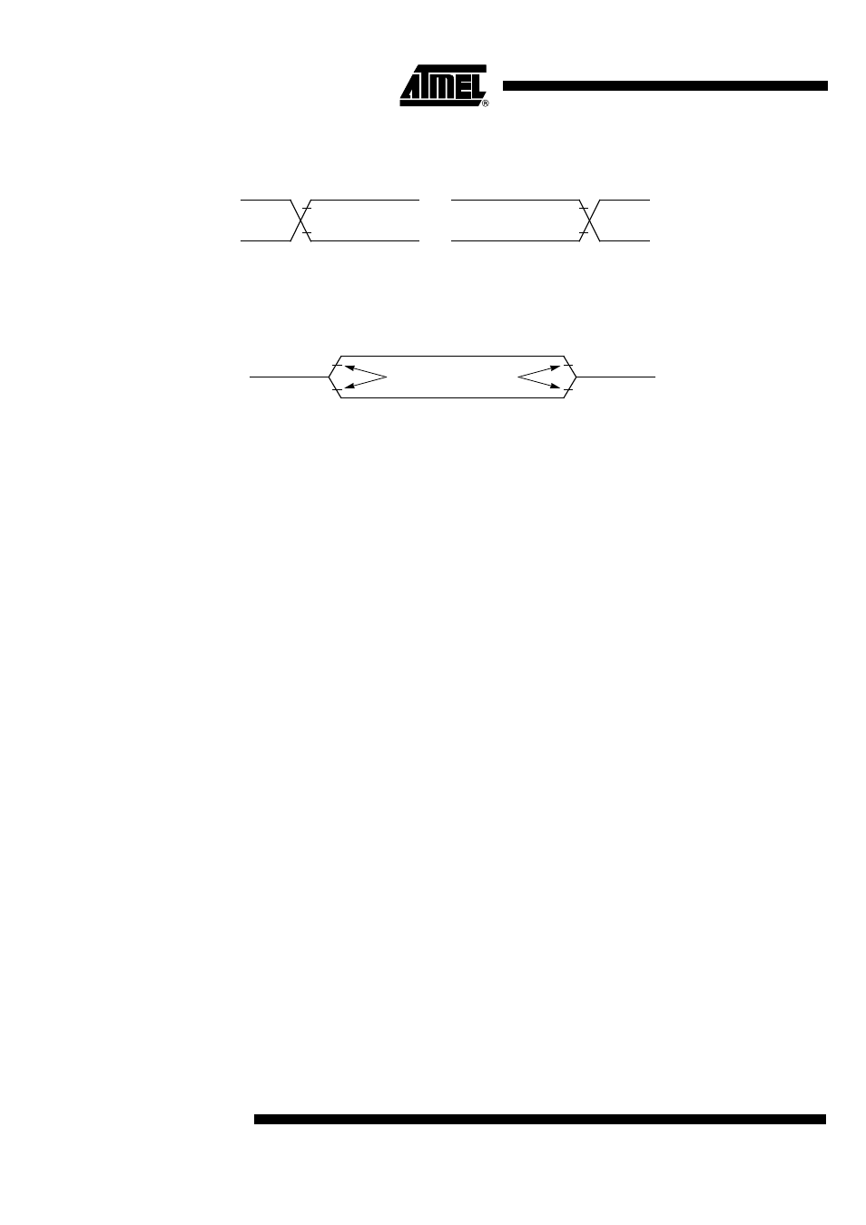
Figure 134. AC Testing Input/Output Waveforms
Notes:
1. During AC testing, all inputs are driven at
V
DD
-0.5V for a logic 1 and 0.45V for a logic 0.
2. Timing measurements are made on all outputs at V
IH
min for a logic 1 and V
IL
max for a logic 0.
Figure 135. Float Waveforms
Note:
For timing purposes, a port pin is no longer floating when a 100 mV change from load voltage occurs and begins to float when a
100 mV change from the loading V
OH
/V
OL
level occurs with I
OL
/I
OH
=
±
20 mA.
0.45 V
DD
- 0.5
0.7
V
DD
0.3
V
DD
V
IH
min
V
IL
max
INPUTS
OUTPUTS
V
LOAD
V
OH
- 0.1V
V
OL
+ 0.1V
V
LOAD
+ 0.1V
V
LOAD
- 0.1V
Timing Reference Points
See also other documents in the category Rainbow Electronics Sensors:
- MAX5151 (16 pages)
- MAXQ3108 (64 pages)
- MAX5661 (39 pages)
- MAX6691 (7 pages)
- MAX5362 (12 pages)
- ADC10158 (26 pages)
- MAX8922L (14 pages)
- MAX8596Z (8 pages)
- MAX7491 (18 pages)
- MAX15040 (15 pages)
- MAX5177 (16 pages)
- ADC08138 (22 pages)
- MAX5961 (42 pages)
- T89C51RD2 (86 pages)
- MAX16055 (9 pages)
- MAX6659 (17 pages)
- ADC0820 (20 pages)
- MAX6678 (19 pages)
- MAX8884Z (15 pages)
- MAX16915 (9 pages)
- MAX8620 (18 pages)
- MAX5144 (12 pages)
- MAX6670 (8 pages)
- MAX8760 (39 pages)
- W78C32C (14 pages)
- MX7533 (8 pages)
- MAX8727 (13 pages)
- MAX9053 (15 pages)
- W78C54 (16 pages)
- MAX8614B (15 pages)
- W90N740 (219 pages)
- MAX6626 (13 pages)
- ADC10738 (30 pages)
- MAX17000 (31 pages)
- MAX5051 (21 pages)
- MAXQ1004 (18 pages)
- MAX6871 (51 pages)
- MX7847 (12 pages)
- MAX6608 (6 pages)
- MAX17083 (15 pages)
- MAX6641 (17 pages)
- MAX5251 (16 pages)
- MAX6338 (8 pages)
- MAX6690 (16 pages)
- MAX8668 (18 pages)