Figure 97) – Rainbow Electronics AT89C5132 User Manual
Page 100
100
AT8xC5132
4173A–8051–08/02
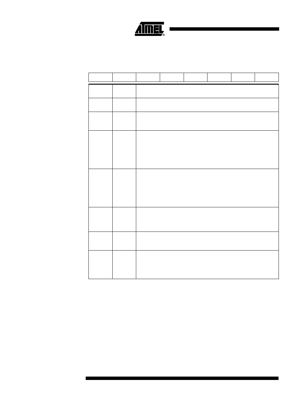
Table 97. MMSTA Register
MMSTA (S:DEh Read Only) – MMC Control and Status Register
Reset Value = 0000 0000b
7
6
5
4
3
2
1
0
-
-
CBUSY
CRC16S
DATFS
CRC7S
RESPFS
CFLCK
Bit
Number
Bit
Mnemonic
Description
7 - 6
-
Reserved
The values read from these Bits are always 0. Do not set these Bits.
5
CBUSY
Card Busy Flag
Set by hardware when the card sends a busy state on the data line.
Cleared by hardware when the card no more sends a busy state on the data line.
4
CRC16S
CRC16 Status Bit
Transmission mode
Set by hardware when the token response reports a good CRC.
Cleared by hardware when the token response reports a bad CRC.
Reception mode
Set by hardware when the CRC16 received in the data block is correct.
Cleared by hardware when the CRC16 received in the data block is not correct.
3
DATFS
Data Format Status Bit
Transmission mode
Set by hardware when the format of the token response is correct.
Cleared by hardware when the format of the token response is not correct.
Reception mode
Set by hardware when the format of the frame is correct.
Cleared by hardware when the format of the frame is not correct.
2
CRC7S
CRC7 Status Bit
Set by hardware when the CRC7 computed in the response is correct.
Cleared by hardware when the CRC7 computed in the response is not correct.
This bit is not relevant when CRCDIS is set.
1
RESPFS
Response Format Status Bit
Set by hardware when the format of a response is correct.
Cleared by hardware when the format of a response is not correct.
0
CFLCK
Command FIFO Lock Bit
Set by hardware to signal user not to write in the transmit command FIFO: busy
state.
Cleared by hardware to signal user the transmit command FIFO is available: idle
state.