Analog comparator, Atmega161(l) – Rainbow Electronics ATmega161L User Manual
Page 81
81
ATmega161(L)
1228C–AVR–08/02
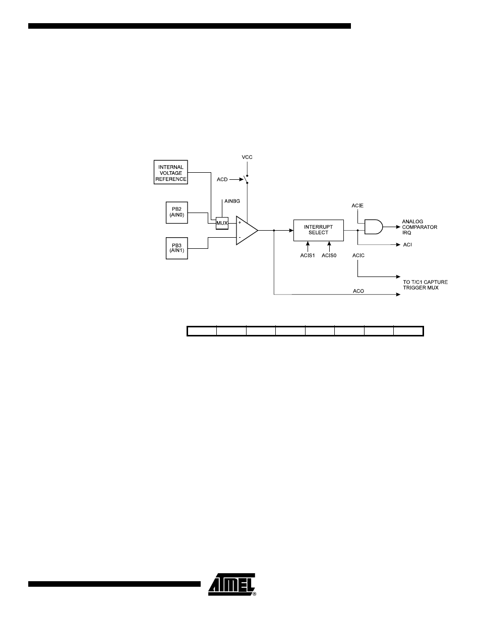
Analog Comparator
The Analog Comparator compares the input values on the positive input PB2 (AIN0) and
negative input PB3 (AIN1). When the voltage on the positive input PB2 (AIN0) is higher
than the voltage on the negative input PB3 (AIN1), the Analog Comparator Output
(ACO) is set (one). The comparator’s output can be set to trigger the Timer/Counter1
Input Capture function. In addition, the comparator can trigger a separate interrupt,
exclusive to the Analog Comparator. The user can select interrupt triggering on compar-
ator output rise, fall or toggle. A block diagram of the comparator and its surrounding
logic is shown in Figure 48.
Figure 48. Analog Comparator Block Diagram
Analog Comparator Control
and Status Register – ACSR
• Bit 7
–
ACD: Analog Comparator Disable
When this bit is set (one), the power to the Analog Comparator is switched off. This bit
can be set at any time to turn off the Analog Comparator. This will reduce power con-
sumption in active and Idle mode. When changing the ACD bit, the Analog Comparator
Interrupt must be disabled by clearing the ACIE bit in ACSR. Otherwise, an interrupt can
occur when the bit is changed.
• Bit 6
–
AINBG: Analog Comparator Bandgap Select
When this bit is set, a fixed bandgap voltage of 1.22 ± 0.05V replaces the normal input
to the positive input (AIN0) of the comparator. When this bit is cleared, the normal input
pin PB2 is applied to the positive input of the comparator.
• Bit 5
–
ACO: Analog Comparator Output
ACO is directly connected to the comparator output.
Bit
7
6
5
4
3
2
1
0
$08 ($28)
ACD
AINBG
ACO
ACI
ACIE
ACIC
ACIS1
ACIS0
ACSR
Read/Write
R/W
R/W
R
R/W
R/W
R/W
R/W
R/W
Initial Value
0
0
N/A
0
0
0
0
0