Reading the fuse and lock bits, Reading the signature bytes, Parallel programming characteristics – Rainbow Electronics ATmega161L User Manual
Page 124: Atmega161(l)
124
ATmega161(L)
1228C–AVR–08/02
Reading the Fuse and Lock
Bits
The algorithm for reading the Fuse and Lock bits is as follows (refer to “Programming
the Flash” on page 120 for details on command loading):
1.
A: Load Command “0000 0100”.
2.
Set OE to “0”, and BS to “0”. The status of the Fuse bits can now be read at
DATA (“0” means programmed).
Bit 6 = BOOTRST Fuse bit
Bit 5 = SPIEN Fuse bit
Bit 4 = SUT Fuse bit
Bit 3 = “1”. This bit is reserved and must be left unprogrammed (“1”).
Bits 2 - 0 = CKSEL2..0 Fuse bits
3.
Set OE to “0”, and BS to “1”. The status of the Lock bits can now be read at
DATA (“0” means programmed).
Bit 5 = Boot Lock Bit12
Bit 4 = Boot Lock Bit11
Bit 3 = Boot Lock Bit02
Bit 2 = Boot Lock Bit01
Bit 1 = Lock Bit2
Bit 0 = Lock Bit1
4.
Set OE to “1”.
Reading the Signature Bytes
The algorithm for reading the Signature bytes is as follows (refer to “Programming the
Flash” on page 120 for details on command and address loading):
1.
A: Load Command “0000 1000”.
2.
C: Load Address Low Byte ($00 - $02).
Set OE to “0”, and BS to “0”. The selected Signature byte can now be read at DATA.
3.
Set OE to “1”.
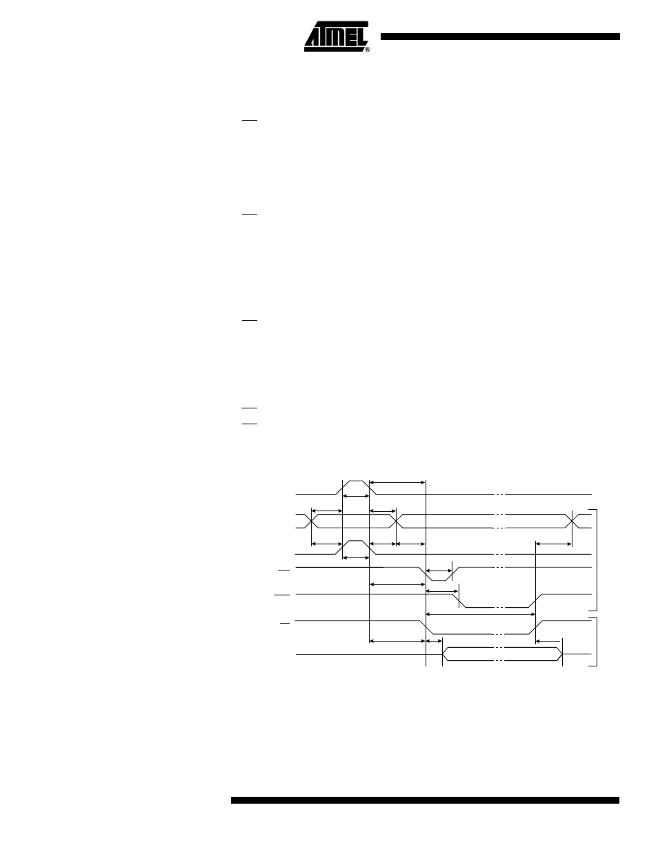
Parallel Programming
Characteristics
Figure 79. Parallel Programming Timing
Data & Control
(DATA, XA0/1, BS1)
DATA
W
rite
Read
XTAL1
t
XHXL
t
WLWH
t
DVXH
t
XLOL
t
OLDV
t
XLDX
t
PLWL
t
WLRH
WR
RDY/BSY
OE
PAGEL
t
PHPL
t
PLBX
t
BVXH
t
XLWL
t
RHBX
t
OHDZ
t
BVWL
WLRL