Atmega161(l) – Rainbow Electronics ATmega161L User Manual
Page 59
59
ATmega161(L)
1228C–AVR–08/02
WDTOE bit is set (one). To disable an enabled Watchdog Timer, the following proce-
dure must be followed:
1.
In the same operation, write a logical “1” to WDTOE and WDE. A logical “1” must
be written to WDE even though it is set to one before the disable operation
starts.
2.
Within the next four clock cycles, write a logical “0” to WDE. This disables the
Watchdog.
• Bits 2..0
–
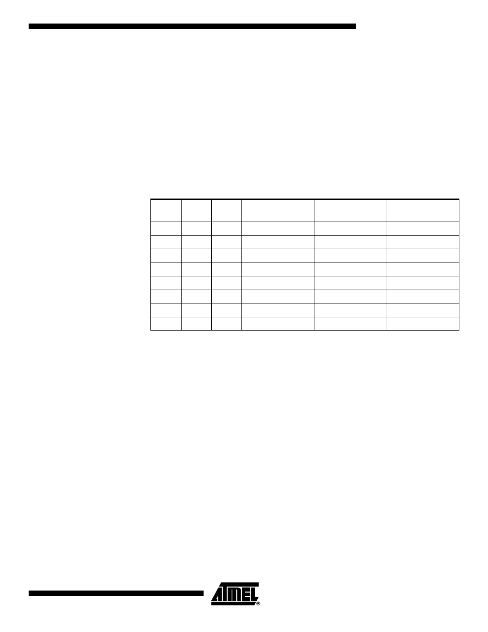
WDP2, WDP1, WDP0: Watchdog Timer Prescaler 2, 1 and 0
The WDP2, WDP1 and WDP0 bits determine the Watchdog Timer prescaling when the
Watchdog Timer is enabled. The different prescaling values and their corresponding
time-out periods are shown in Table 20.
Note:
1. The frequency of the Watchdog Oscillator is voltage-dependent, as shown in the
Electrical Characteristics section.
The WDR (Watchdog Reset) instruction should always be executed before the
Watchdog Timer is enabled. This ensures that the reset period will be in accordance
with the Watchdog Timer prescale settings. If the Watchdog Timer is enabled without
reset, the Watchdog Timer may not start counting from zero.
To avoid unintentional MCU Reset, the Watchdog Timer should be disabled or reset
before changing the Watchdog Timer Prescale Select.
Table 20. Watchdog Timer Prescale Select
(1)
WDP2
WDP1
WDP0
Number of WDT
Oscillator Cycles
Typical Time-out
at V
CC
= 3.0V
Typical Time-out
at V
CC
= 5.0V
0
0
0
16K
47 ms
15 ms
0
0
1
32K
94 ms
30 ms
0
1
0
64K
0.19 s
60 ms
0
1
1
128K
0.38 s
0.12 s
1
0
0
256K
0.75 s
0.24 s
1
0
1
512K
1.5 s
0.49 s
1
1
0
1,024K
3.0 s
0.97 s
1
1
1
2,048K
6.0 s
1.9 s