Atmega161(l) – Rainbow Electronics ATmega161L User Manual
Page 43
43
ATmega161(L)
1228C–AVR–08/02
prescaling of 1 is used, and the compare register is set to C, the timer will count as fol-
lows if CTC0/CTC2 is set:
... | C-1 | C | 0 | 1 | ...
When the prescaler is set to divide by 8, the timer will count like this:
... | C-1, C-1, C-1, C-1, C-1, C-1, C-1, C-1 | C, C, C, C, C, C, C, C | 0, 0, 0, 0, 0, 0, 0, 0 |
1, 1, 1, ...
In PWM mode, this bit has a different function. If the CTC0 or CTC2 bit is cleared in
PWM mode, the Timer/Counter acts as an up/down counter. If the CTC0 or CTC2 bit is
set (one), the Timer/Counter wraps when it reaches $FF. Refer to page 44 for a detailed
description.
• Bits 2, 1, 0
–
CS02, CS01, CS00/CS22, CS21, CS20: Clock Select Bits 2, 1 and 0
The Clock Select bits 2, 1, and 0 define the prescaling source of Timer/Counter0 and
Timer/Counter2.
The Stop condition provides a Timer Enable/Disable function. The prescaled modes are
scaled directly from the CK Oscillator clock for Timer/Counter0 and PCK2 for
Timer/Counter2. If the external pin modes are used for Timer/Counter0, transitions on
PB0/(T0) will clock the counter even if the pin is configured as an output. This feature
can give the user software control of the counting.
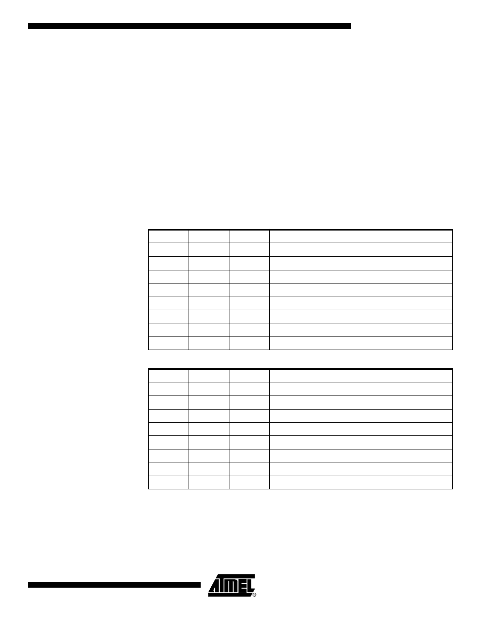
Table 10. Clock 0 Prescale Select
CS02
CS01
CS00
Description
0
0
0
Stop, the Timer/Counter0 is stopped.
0
0
1
CK
0
1
0
CK/8
0
1
1
CK/64
1
0
0
CK/256
1
0
1
CK/1024
1
1
0
External Pin PB0(T0), falling edge
1
1
1
External Pin PB0(T0), rising edge
Table 11. Clock 2 Prescale Select
CS22
CS21
CS20
Description
0
0
0
Stop, the Timer/Counter2 is stopped.
0
0
1
PCK2
0
1
0
PCK2/8
0
1
1
PCK2/32
1
0
0
PCK2/64
1
0
1
PCK2/128
1
1
0
PCK2/256
1
1
1
PCK2/1024