Asynchronous status register – assr, Atmega161(l) – Rainbow Electronics ATmega161L User Manual
Page 47
47
ATmega161(L)
1228C–AVR–08/02
In up/down PWM mode, the Timer Overflow Flag (TOV0 or TOV2) is set when the
counter advances from $00. In overflow PWM mode, the Timer Overflow Flag is set as
in normal Timer/Counter mode. Timer Overflow Interrupt0 and 2 operate exactly as in
normal Timer/Counter mode, i.e., they are executed when TOV0 or TOV2 are set, pro-
vided that Timer Overflow Interrupt and global interrupts are enabled. This also applies
to the Timer Output Compare flag and interrupt.
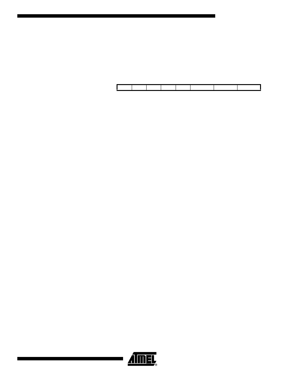
Asynchronous Status
Register – ASSR
• Bits 7..4
–
Res: Reserved Bits
These bits are reserved bits in the ATmega161 and always read as zero.
• Bit 3
–
AS2: Asynchronous Timer/Counter2 Mode
When this bit is cleared (zero), Timer/Counter2 is clocked from the internal system
clock, CK. If AS2 is set, the Timer/Counter2 is clocked from the TOSC1 pin. Pins PD4
and PD5 become connected to a crystal Oscillator and cannot be used as general I/O
pins. When the value of this bit is changed, the contents of TCNT2, OCR2 and TCCR2
might get corrupted.
• Bit 2
–
TCN2UB: Timer/Counter2 Update Busy
When Timer/Counter2 operates asynchronously and TCNT2 is written, this bit becomes
set (one). When TCNT2 has been updated from the temporary storage register, this bit
is cleared (zero) by hardware. A logical “0” in this bit indicates that TCNT2 is ready to be
updated with a new value.
• Bit 1
–
OCR2UB: Output Compare Register2 Update Busy
When Timer/Counter2 operates asynchronously and OCR2 is written, this bit becomes
set (one). When OCR2 has been updated from the temporary storage register, this bit is
cleared (zero) by hardware. A logical “0” in this bit indicates that OCR2 is ready to be
updated with a new value.
• Bit 0
–
TCR2UB: Timer/Counter Control Register2 Update Busy
When Timer/Counter2 operates asynchronously and TCCR2 is written, this bit becomes
set (one). When TCCR2 has been updated from the temporary storage register, this bit
is cleared (zero) by hardware. A logical “0” in this bit indicates that TCCR2 is ready to be
updated with a new value.
If a write is performed to any of the three Timer/Counter2 Registers while its update
Busy Flag is set (one), the updated value might get corrupted and cause an uninten-
tional interrupt to occur.
The mechanisms for reading TCNT2, OCR2 and TCCR2 are different. When reading
TCNT2, the actual timer value is read. When reading OCR2 or TCCR2, the value in the
temporary storage register is read.
Bit
7
6
5
4
3
2
1
0
$26 ($46)
–
–
–
–
AS2
TCN2UB
OCR2UB
TCR2UB
ASSR
Read/Write
R
R
R
R
R/W
R
R
R
Initial Value
0
0
0
0
0
0
0
0