Pwm modes (up/down and overflow), Atmega161(l) – Rainbow Electronics ATmega161L User Manual
Page 45
45
ATmega161(L)
1228C–AVR–08/02
PWM Modes (Up/Down and
Overflow)
T he two different PWM mod es are selected by the CT C0 or CTC 2 bit in the
Timer/Counter Control Registers – TCCR0 or TCCR2, respectively.
If CTC0/CTC2 is cleared and PWM mode is selected, the Timer/Counter acts as an
up/down counter, counting up from $00 to $FF, where it turns and counts down again to
zero before the cycle is repeated. When the counter value matches the contents of the
Output Compare Register, the PB0(OC0/PWM0) or PB1(OC2/PWM2) pin is set or
cleared according to the settings of the COMn1/COMn0 bits in the Timer/Counter Con-
trol Registers TCCR0 or TCCR2.
If CTC0/CTC2 is set and PWM mode is selected, the Timer/Counters will wrap and start
counting from $00 after reaching $FF. The PB0(OC0/PWM0) or PB1(OC2/PWM2) pin
will be set or cleared according to the settings of COMn1/COMn0 on a Timer/Counter
overflow or when the counter value matches the contents of the Output Compare Regis-
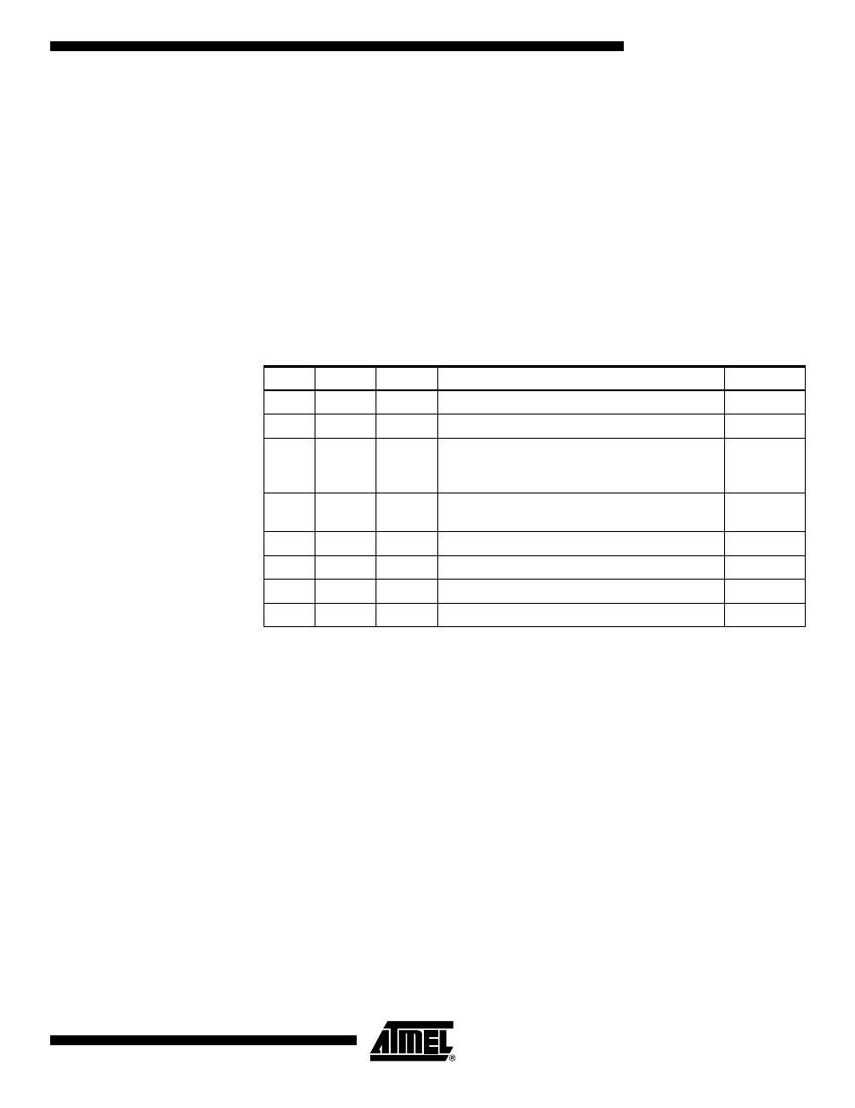
ter. Refer to Table 12 for details.
Note:
1. n = 0 or 2
Note that in PWM mode, the value to be written to the Output Compare Register is first
transferred to a tem porary location and then l atched i nto the OCR when the
Timer/Counter reaches $FF. This prevents the occurrence of odd-length PWM pulses
(glitches) in the event of an unsynchronized OCR0 or OCR2 write. See Figure 33 and
Figure 34 for examples.
Table 12. Compare Mode Select in PWM Mode
(1)
CTCn
COMn1
COMn0
Effect on Compare Pin
Frequency
0
0
0
Not connected
0
0
1
Not connected
0
1
0
Cleared on compare match, up-counting. Set on
compare match, down-counting (non-inverted
PWM).
f
TCK0/2
/510
0
1
1
Cleared on compare match, down-counting. Set
on compare match, up-counting (inverted PWM).
f
TCK0/2
/510
1
0
0
Not connected
1
0
1
Not connected
1
1
0
Cleared on compare match, set on overflow
f
TCK0/2
/256
1
1
1
Set on compare match, cleared on overflow
f
TCK0/2
/256