Bit timer/counters t/c0 and t/c2, Atmega161(l), Bit 0 – Rainbow Electronics ATmega161L User Manual
Page 40
40
ATmega161(L)
1228C–AVR–08/02
• Bit 0
–
PSR10: Prescaler Reset Timer/Counter1 and Timer/Counter0
When this bit is set (one), the Timer/Counter1 and Timer/Counter0 prescaler will be
reset. The bit will be cleared by hardware after the operation is performed. Writing a
zero to this bit will have no effect. Note that Timer/Counter1 and Timer/Counter0 share
the same prescaler and a reset of this prescaler will affect both timers. This bit will
always be read as zero.
8-bit Timer/Counters
T/C0 and T/C2
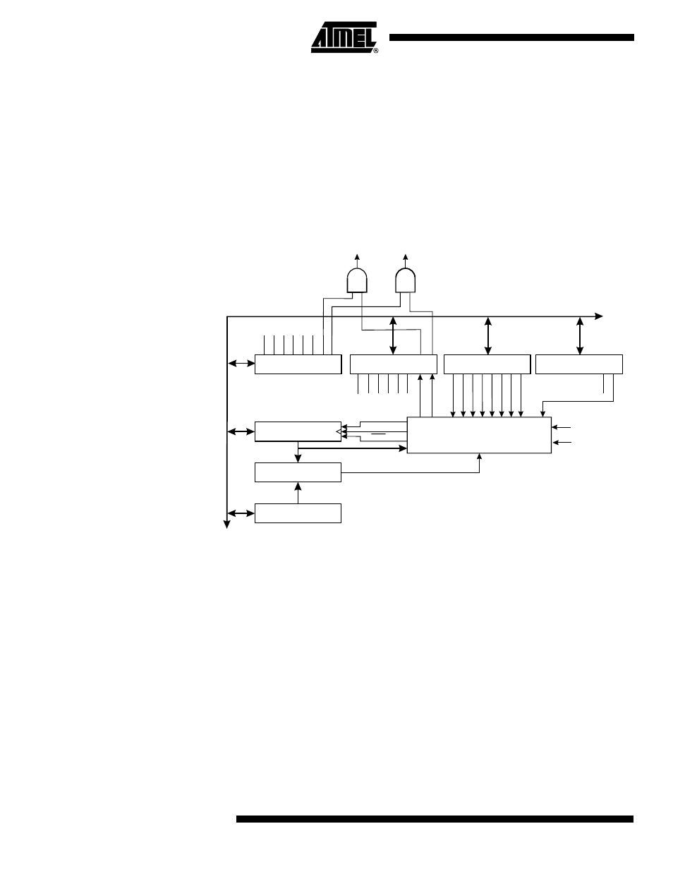
Figure 31 shows the block diagram for Timer/Counter0. Figure 32 shows the block dia-
gram for Timer/Counter2.
Figure 31. Timer/Counter0 Block Diagram
8-BIT DA
T
A
BUS
TIMER INT. FLAG
REGISTER (TIFR)
TIMER/COUNTER0
(TCNT0)
8-BIT COMPARATOR
OUTPUT COMPARE
REGISTER0 (OCR0)
TIMER INT. MASK
REGISTER (TIMSK)
0
0
0
7
7
7
T/C CLK SOURCE
UP/DOWN
T/C CLEAR
CONTROL
LOGIC
TOV1
OCF1B
OCF1A
ICF1
TOV2
OCF2
OCF0
TOV0
CK
T/C0 OVER-
FLOW IRQ
T/C0 COMPARE
MATCH IRQ
OCF0
TOV0
TOIE0
TOIE1
OCIE1A
OCIE1B
TICIE1
TOIE2
OCIE2
OCIE0
T/C0 CONTROL
REGISTER (TCCR0)
CS02
COM01
PWM0
CS01
COM00
CS00
CTC0
FOC0
PSR2
PSR10
SPECIAL FUNCTIONS
IO REGISTER (SFIOR)
T0