General interrupt flag register – gifr, Timer/counter interrupt mask register – timsk, Atmega161(l) – Rainbow Electronics ATmega161L User Manual
Page 31: Bits 4
31
ATmega161(L)
1228C–AVR–08/02
• Bits 4..0
–
Res: Reserved Bits
These bits are reserved bits in the ATmega161 and always read as zero.
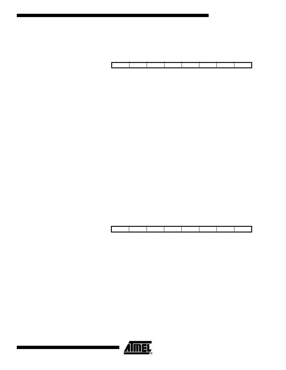
General Interrupt Flag
Register – GIFR
• Bit 7
–
INTF1: External Interrupt Flag1
When an event on the INT1 pin triggers an interrupt request, INTF1 becomes set (one).
If the I-bit in SREG and the INT1 bit in GIMSK are set (one), the MCU will jump to the
Interrupt Vector at address $004. The Flag is cleared when the interrupt routine is exe-
cuted. Alternatively, the Flag can be cleared by writing a logical “1” to it.
• Bit 6
–
INTF0: External Interrupt Flag0
When an event on the INT0 pin triggers an interrupt request, INTF0 becomes set (one).
If the I-bit in SREG and the INT0 bit in GIMSK are set (one), the MCU will jump to the
Interrupt Vector at address $002. The Flag is cleared when the interrupt routine is exe-
cuted. Alternatively, the Flag can be cleared by writing a logical “1” to it.
• Bit 5
–
INTF2: External Interrupt Flag2
When an event on the INT2 pin triggers an interrupt request, INTF2 becomes set (one).
If the I-bit in SREG and the INT2 bit in GIMSK are set (one), the MCU will jump to the
Interrupt Vector at address $006. The Flag is cleared when the interrupt routine is exe-
cuted. Alternatively, the Flag can be cleared by writing a logical “1” to it.
• Bits 4..0
–
Res: Reserved Bits
These bits are reserved bits in the ATmega161 and always read as zero.
Timer/Counter Interrupt Mask
Register – TIMSK
• Bit 7
–
TOIE1: Timer/Counter1 Overflow Interrupt Enable
When the TOIE1 bit is set (one) and the I-bit in the Status Register is set (one), the
Timer/Counter1 Overflow interrupt is enabled. The corresponding interrupt (at Vector
$012) is executed if an overflow in Timer/Counter1 occurs, i.e., when the TOV1 bit is set
in the Timer/Counter Interrupt Flag Register (TIFR).
• Bit 6
–
OCE1A: Timer/Counter1 Output CompareA Match Interrupt Enable
When the OCIE1A bit is set (one) and the I-bit in the Status Register is set (one), the
Timer/Counter1 CompareA Match interrupt is enabled. The corresponding interrupt (at
Vector $00e) is executed if a Compare A Match in Timer/Counter1 occurs, i.e., when the
OCF1A bit is set in the Timer/Counter Interrupt Flag Register (TIFR).
Bit
7
6
5
4
3
2
1
0
$3A ($5A)
INTF1
INTF0
INTF2
–
–
–
–
–
GIFR
Read/Write
R/W
R/W
R/W
R
R
R
R
R
Initial Value
0
0
0
0
0
0
0
0
Bit
7
6
5
4
3
2
1
0
$39 ($59)
TOIE1
OCIE1A
OCIE1B
TOIE2
TICIE1
OCIE2
TOIE0
OCIE0
TIMSK
Read/Write
R/W
R/W
R/W
R/W
R/W
R/W
R/W
R/W
Initial Value
0
0
0
0
0
0
0
0