Atmega161(l) – Rainbow Electronics ATmega161L User Manual
Page 57
57
ATmega161(L)
1228C–AVR–08/02
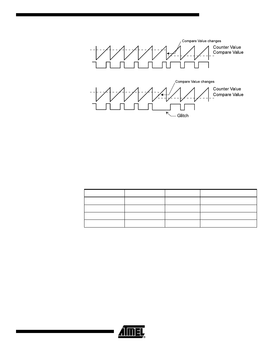
Figure 38. Effects of Unsynchronized OCR1 Latching in Overflow Mode
1
Note:
1. Note: X = A or B
During the time between the write and the latch operation, a read from OCR1A or
OCR1B will read the contents of the temporary location. This means that the most
recently written value always will read out of OCR1A/B.
When the OCR1X contains $0000 or TOP, and the up/down PWM mode is selected, the
output OC1A/OC1B is updated to low or high on the next compare match according to
the settings of COM1A1/COM1A0 or COM1B1/COM1B0. This is shown in Table 19. In
overflow PWM mode, the output OC1A/OC1B is held low or high only when the Output
Compare Register contains TOP.
Note:
1. X = A or B
In overflow PWM mode, the table above is only valid for OCR1X = TOP.
In up/down PWM mode, the Timer Overflow Flag1 (TOV1) is set when the counter
advances from $0000. In overflow PWM mode, the Timer Overflow Flag is set as in nor-
mal Timer/Counter mode. Timer Overflow Interrupt1 operates exactly as in normal
Timer/Counter mode, i.e., it is executed when TOV1 is set, provided that Timer Overflow
Interrupt1 and global interrupts are enabled. This also applies to the Timer Output
Compare1 Flags and interrupts.
Table 19. PWM Outputs OCR1X = $0000 or TOP
(1)
COM1X1
COM1X0
OCR1X
Output OC1X
1
0
$0000
L
1
0
TOP
H
1
1
$0000
H
1
1
TOP
L
PWM Output OC1x
PWM Output OC1x
Unsynchronized OC1x Latch
Synchronized OC1x Latch