Atmega161(l) – Rainbow Electronics ATmega161L User Manual
Page 128
128
ATmega161(L)
1228C–AVR–08/02
.
Note:
1. a = address high bits
b = address low bits
H = 0 – Low byte, 1 – High Byte
o = data out
i = data in
x = don’t care
1
= lock bit 1
2
= lock bit 2
3
= Boot Lock Bit1
4
= Boot Lock Bit2
5
= Boot Lock Bit11
6
= Boot Lock Bit12
7 = CKSEL0 Fuse
8 = CKSEL1 Fuse
9 = CKSEL2 Fuse
B = SUT Fuse
C = SPIEN Fuse
D = BOOTRST Fuse
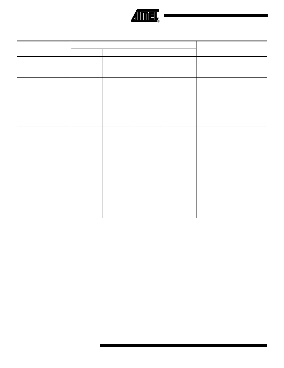
Table 48. Serial Programming Instruction Set
(1)
Instruction
Instruction Format
Operation
Byte 1
Byte 2
Byte 3
Byte 4
Programming Enable
1010 1100
0101 0011
xxxx xxxx
xxxx xxxx
Enable Serial Programming after
RESET goes low.
Chip Erase
1010 1100
100x xxxx
xxxx xxxx
xxxx xxxx
Chip Erase EEPROM and Flash.
Read Program Memory
0010 H000
xxxa aaaa
bbbb bbbb
oooo oooo
Read H (high or low) data o from
Program memory at word address
a:b.
Load Program Memory
Page
0100 H000
xxxx xxxx
xxbb bbbb
iiii iiii
Write H (high or low) data i to
Program memory page at word
address b.
Write Program Memory
Page
0100 1100
xxxa aaaa
bb
xx xxxx
iiii iiii
Write Program memory page at
address a:b.
Read EEPROM Memory
1010 0000
xxxx xxxa
bbbb bbbb
oooo oooo
Read data o from EEPROM
memory at address a:b.
Write EEPROM Memory
1100 0000
xxxx xxxa
bbbb bbbb
iiii iiii
Write data i to EEPROM memory at
address a:b.
Read Lock bits
0101 1000
xxxx xxxx
xxxx xxxx
xx
65 4321
Read Lock bits. “0” = programmed,
“1” = unprogrammed.
Write Lock bits
1010 1100
111x xxxx
xxxx xxxx
11
65 4321
Write Lock bits. Set bits
6
-
1
= “0”
to program Lock bits.
Read Signature Byte
0011 0000
xxxx xxxx
xxxx xxbb
oooo oooo
Read Signature byte o at address
b.
Write Fuse bits
1010 1100
101x xxxx
xxxx xxxx
1D1B 1987
Set bits D - B, 9 - 7 = “0” to
program, “1” to unprogram
Read Fuse bits
0101 0000
xxxx xxxx
xxxx xxxx
xDCB 1987
Read Fuse bits. “0” = programmed,
“1” = unprogrammed