Overview, Registers, Atmega128(l) – Rainbow Electronics ATmega128L User Manual
Page 87
87
ATmega128(L)
2467B–09/01
8-bit Timer/Counter0 with PWM and Asynchronous Operation
Timer/Counter0 is a general purpose, single channel, 8-bit Timer/Counter module. The
main features are:
•
Single Channel Counter
•
Clear Timer on Compare Match (Auto Reload)
•
Glitch-free, Phase Correct Pulse Width Modulator (PWM)
•
Frequency Generator
•
10-bit Clock Prescaler
•
Overflow and Compare Match Interrupt Sources (TOV0 and OCF0)
•
Allows Clocking from External 32 kHz Watch Crystal Independent of the I/O Clock
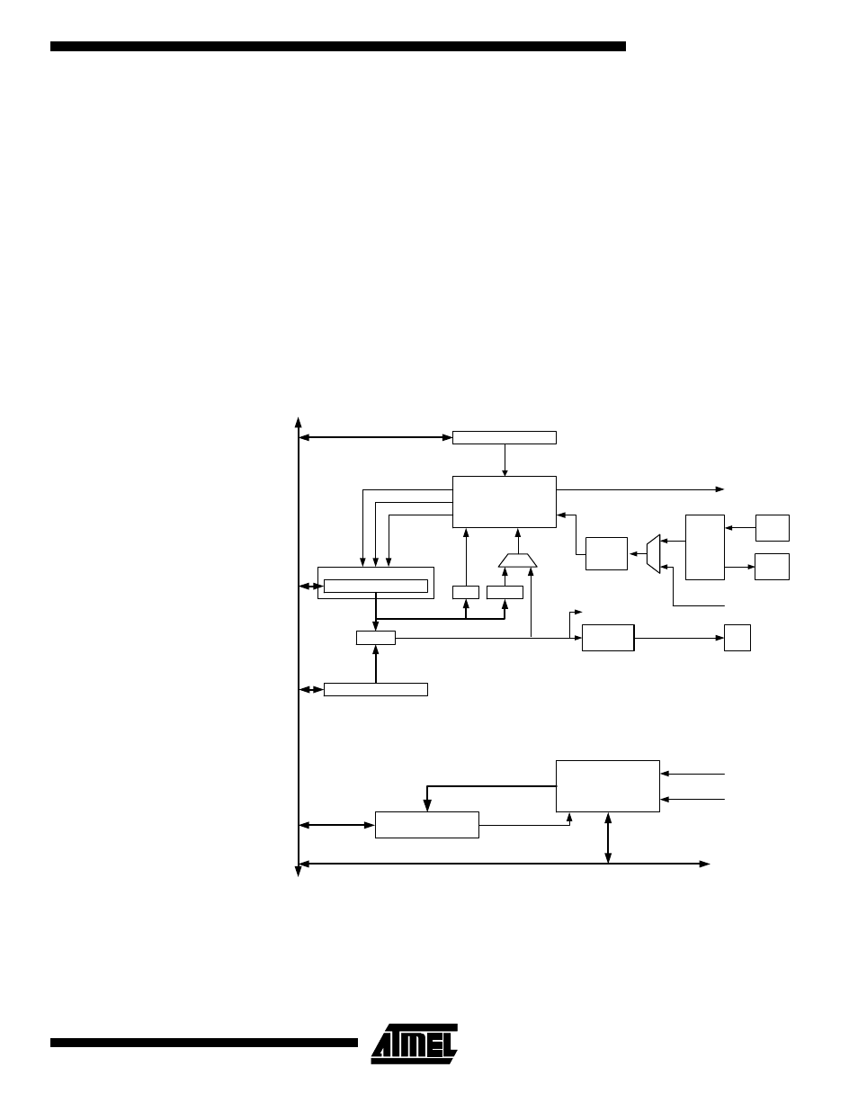
Overview
A simplified block diagram of the 8-bit Timer/Counter is shown in
Figure 33. For the
actual placement of I/O pins, refer to
“Pin Configurations” on page 2. CPU accessible
I/O registers, including I/O bits and I/O pins, are shown in bold. The device-specific I/O
register and bit locations are listed in the
“8-bit Timer/Counter Register Description” on
Figure 33. 8-bit Timer/Counter Block Diagram
Registers
The Timer/Counter (TCNT0) and Output Compare Register (OCR0) are 8-bit registers.
Interrupt request (shorten as Int.Req.) signals are all visible in the Timer Interrupt Flag
Register (TIFR). All interrupts are individually masked with the Timer Interrupt Mask reg-
ister (TIMSK). TIFR and TIMSK are not shown in the figure since these registers are
shared by other timer units.
Timer/Counter
D
ATA
B
U
S
=
TCNTn
Waveform
Generation
OCn
= 0
Control Logic
=
0xFF
TOP
BOTTOM
count
clear
direction
TOVn
(Int.Req.)
OCn
(Int.Req.)
Synchronization Unit
OCRn
TCCRn
ASSRn
Status flags
clk
I/O
clk
ASY
Synchronized Status flags
asynchronous mode
select (ASn)
TOSC1
T/C
Oscillator
TOSC2
Prescaler
clk
Tn
clk
I/O