Atmega103 compatibility, Using the external memory interface, Figure 11 – Rainbow Electronics ATmega128L User Manual
Page 25: Atmega128(l)
25
ATmega128(L)
2467B–09/01
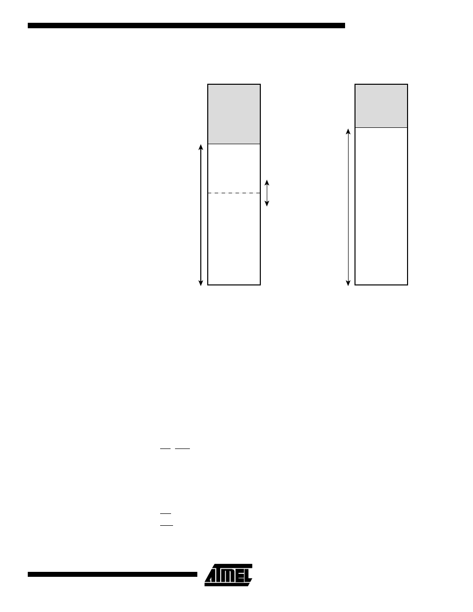
Figure 11. External Memory with Sector Select
Note:
ATmega128 in non ATmega103 compatibility mode: Memory Configuration A is available
(Memory Configuration B N/A)
ATmega128 in ATmega103 compatibility mode: Memory Configuration B is available
(Memory Configuration A N/A)
ATmega103 Compatibility
Both External Memory Control Registers (XMCRA and XMCRB) are placed in Extended
I/O space. In ATmega103 Compatibility mode, these registers are not available, and the
features selected by these registers are not available. The device is still ATmega103
compatible, as these features did not exist in ATmega103. The limitations in
ATmega103 compatibility mode are:
•
Only two wait-states settings are available (SRW1n = 0b00 and SRW1n = 0b01).
•
The number of bits that are assigned to address high byte are fixed.
•
The external memory section can not be divided into sectors with different wait-state
settings.
•
Bus-keeper is not available.
•
RD, WR and ALE pins are output only (Port G in ATmega128).
Using the External Memory
Interface
The interface consists of:
•
AD7:0: Multiplexed low-order address bus and data bus.
•
A15:8: High-order address bus (configurable number of bits).
•
ALE: Address latch enable.
•
RD: Read strobe.
•
WR: Write strobe.
Memory Configuration A
0x0000
0x10FF
External Memory
(0-60K x 8)
0xFFFF
Internal memory
SRL[2..0]
SRW11
SRW10
SRW01
SRW00
Lower sector
Upper sector
0x1100
Memory Configuration B
0x0000
External Memory
(0-60K x 8)
0xFFFF
Internal memory
SRW10
0x0FFF
0x1000