Table 67 on, Atmega128(l) – Rainbow Electronics ATmega128L User Manual
Page 152
152
ATmega128(L)
2467B–09/01
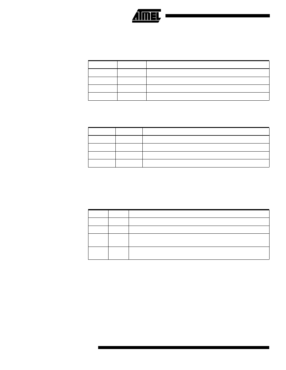
When OC2 is connected to the pin, the function of the COM21:0 bits depends on the
WGM21:0 bit setting.
Table 65 shows the COM21:0 bit functionality when the WGM21:0
bits are set to a normal or CTC mode (non-PWM).
Table 66 shows the COM21:0 bit functionality when the WGM21:0 bits are set to fast
PWM mode.
Note:
1. A special case occurs when OCR2 equals TOP and COM21 is set. In this case, the
compare match is ignored, but the set or clear is done at TOP. See
on page 146 for more details.
Table 67 shows the COM21:0 bit functionality when the WGM21:0 bits are set to phase
correct PWM mode.
Note:
1. A special case occurs when OCR2 equals TOP and COM21 is set. In this case, the
compare match is ignored, but the set or clear is done at TOP. See
PWM Mode” on page 147 for more details.
• Bit 2:0 - CS22:0: Clock Select
The three clock select bits select the clock source to be used by the Timer/Counter.
Table 65. Compare Output Mode, Non-PWM Mode
COM21
COM20
Description
0
0
Normal port operation,
OC
2 disconnected.
0
1
Toggle
OC
2 on compare match
1
0
Clear
OC
2 on compare match
1
1
Set
OC
2 on compare match
Table 66. Compare Output Mode, Fast PWM Mode
COM21
COM20
Description
0
0
Normal port operation,
OC
2 disconnected.
0
1
Reserved
1
0
Clear
OC
2 on compare match, set OC2 at TOP
1
1
Set
OC
2 on compare match, clear OC2 at TOP
Table 67. Compare Output Mode, Phase Correct PWM Mode
COM21
COM20
Description
0
0
Normal port operation,
OC
2 disconnected.
0
1
Reserved
1
0
Clear
OC
2 on compare match when up-counting. Set OC2 on compare
match when downcounting.
1
1
Set
OC
2 on compare match when up-counting. Clear OC2 on compare
match when downcounting.