Table, Am in, Figure 21 – Rainbow Electronics ATmega128L User Manual
Page 46: Table 19 def, Atmega128(l)
46
ATmega128(L)
2467B–09/01
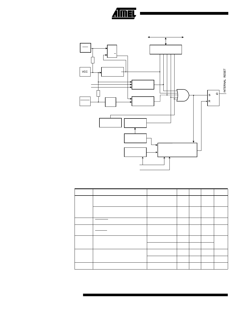
Figure 21. Reset Logic
Notes:
1. Values are guidelines only. Actual values are TBD.
2. The Power-on Reset will not work unless the supply voltage has been below V
POT
(falling)
Table 19. Reset Characteristics
Symbol
Parameter
Condition
Min
Typ
Max
Units
V
POT
Power-on Reset Threshold
Voltage (rising)
TBD
TBD
2.3
V
Power-on Reset Threshold
Voltage (falling)
TBD
TBD
2.3
V
V
RST
RESET Pin Threshold Voltage
TBD
TBD
TBD
V
t
RST
Minimum pulse width on
RESET Pin
TBD
TBD
TBD
ns
V
BOT
Brown-out Reset Threshold
Voltage
BODLEVEL = 1
TBD
2.7
TBD
V
BODLEVEL = 0
TBD
4.0
TBD
t
BOD
Minimum low voltage period for
Brown-out Detection
BODLEVEL = 1
TBD
TBD
TBD
µs
BODLEVEL = 0
TBD
TBD
TBD
µs
V
HYST
Brown-out Detector hysteresis
TBD
50
TBD
mV
MCU Control and Status
Register (MCUCSR)
Brown-Out
Reset Circuit
BODEN
BODLEVEL
Delay Counters
CKSEL[3:0]
CK
TIMEOUT
WDRF
BORF
EXTRF
PORF
DATA BUS
Clock
Generator
SPIKE
FILTER
Pull-up Resistor
JTRF
JTAG Reset
Register
Watchdog
Oscillator
SUT[1:0]
COUNTER RESET
Watchdog
Timer
RESET
Pull-up Resistor
PEN
Reset Circuit
L
D
Q
Q
Power-On Reset
Circuit