External clock, Timer/counter oscillator, Xtal divide control register – xdiv – Rainbow Electronics ATmega128L User Manual
Page 39: Table 15, Atmega128(l)
39
ATmega128(L)
2467B–09/01
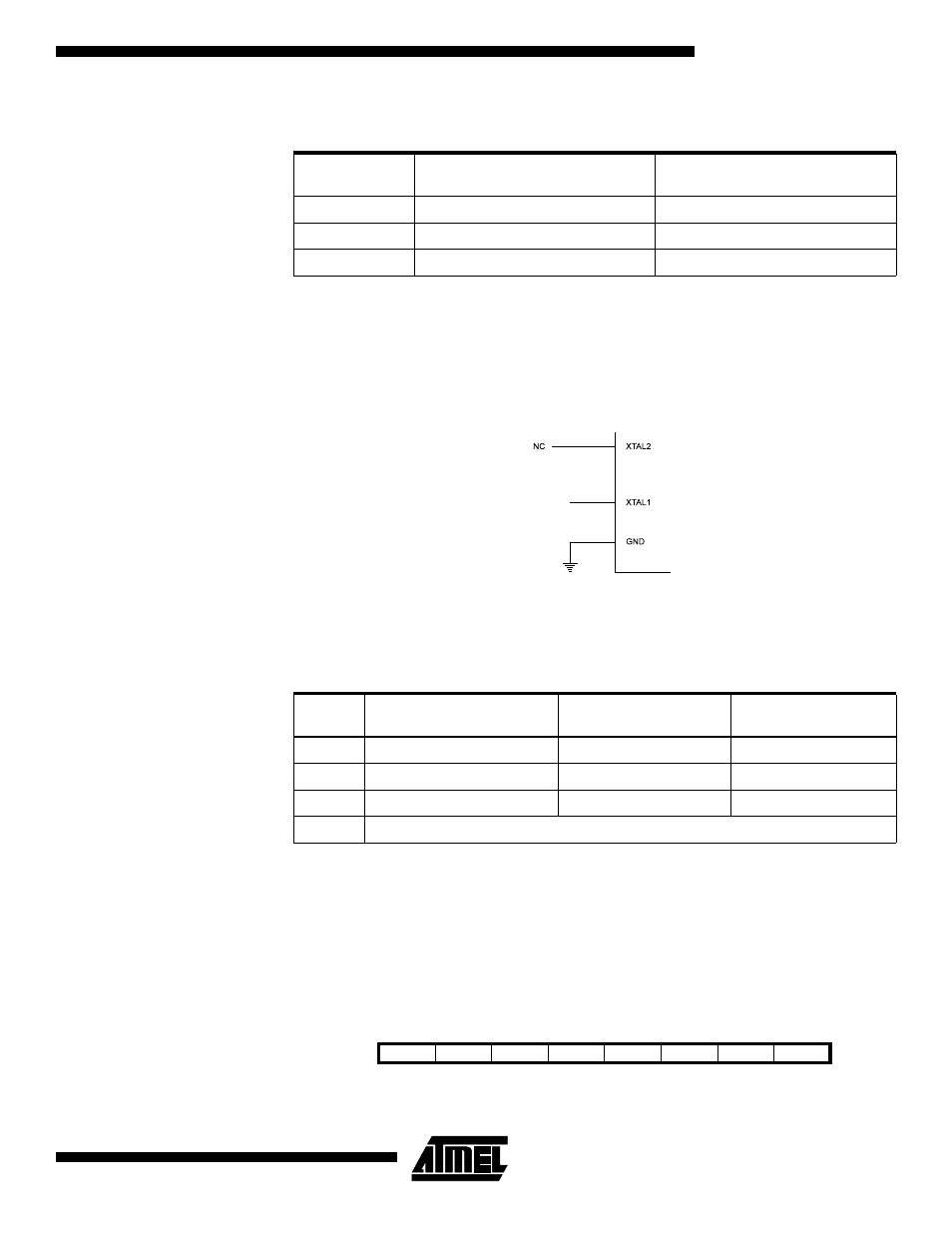
External Clock
To drive the device from an external clock source, XTAL1 should be driven as shown in
Figure 20. To run the device on an external clock, the CKSEL fuses must be pro-
grammed to “0000”. By programming the CKOPT fuse, the user can enable an internal
36 pF capacitor between XTAL1 and GND.
Figure 20. External Clock Drive Configuration
When this clock source is selected, start-up times are determined by the SUT fuses as
shown in
Timer/Counter Oscillator
For AVR microcontrollers with Timer/Counter Oscillator pins (TOSC1 and TOSC2), the
crystal is connected directly between the pins. No external capacitors are needed. The
oscillator is optimized for use with a 32.768 kHz watch crystal. Applying an external
clock source to TOSC1 is not recommended.
XTAL Divide Control Register
– XDIV
The XTAL Divide Control Register is used to divide the Source clock frequency by a
number in the range 2 - 129. This feature can be used to decrease power consumption
when the requirement for processing power is low.
Table 15. Internal RC Oscillator Frequency Range.
OSCCAL Value
Min Frequency in Percentage of
Nominal Frequency (%)
Max Frequency in Percentage of
Nominal Frequency (%)
$00
50
100
$7F
75
150
$FF
100
200
Table 16. Start-up Times for the External Clock Selection
SUT1..0
Start-up Time from Power-
down and Power-save
Additional Delay from
Reset (V
CC
= 5.0V)
Recommended Usage
00
6 CK
–
BOD enabled
01
6 CK
4 ms
Fast rising power
10
6 CK
64 ms
Slowly rising power
11
Reserved
EXTERNAL
CLOCK
SIGNAL
Bit
7
6
5
4
3
2
1
0
XDIVEN
XDIV6
XDIV5
XDIV4
XDIV3
XDIV2
XDIV1
XDIV0
XDIV
Read/Write
R/W
R/W
R/W
R/W
R/W
R/W
R/W
R/W
Initial value
0
0
0
0
0
0
0
0