Brown-out detection, Watchdog reset, Atmega128(l) – Rainbow Electronics ATmega128L User Manual
Page 48
48
ATmega128(L)
2467B–09/01
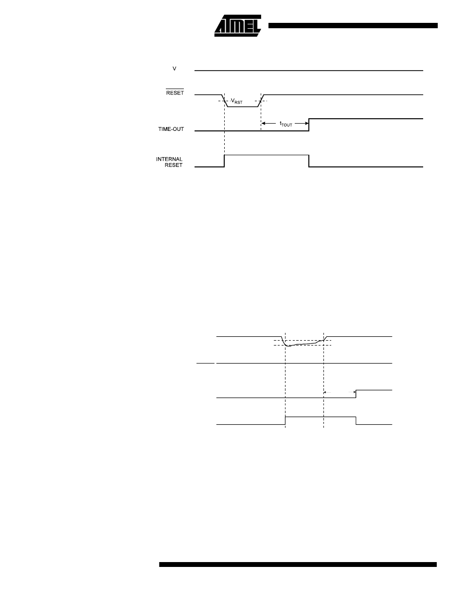
Figure 24. External Reset During Operation
Brown-out Detection
ATmega128 has an on-chip brown-out detection (BOD) circuit for monitoring the V
CC
level during operation by comparing it to a fixed trigger level. The trigger level for the
BOD can be selected by the fuse BODLEVEL to be 2.7V (BODLEVEL unprogrammed),
or 4.0V (BODLEVEL programmed). The trigger level has a hysteresis to ensure spike
free brown-out detection. The hysteresis on the detection level should be interpreted as
V
BOT+
= V
BOT
+ V
HYST
/2 and V
BOT-
= V
BOT
- V
HYST
/2.
The BOD circuit can be enabled/disabled by the fuse BODEN. When the BOD is
enabled (BODEN programmed), and V
CC
decreases to a value below the trigger level
(V
BOT-
in
Figure 25), the Brown-out reset is immediately activated. When V
CC
increases
above the trigger level (V
BOT+
in
Figure 25), the delay counter starts the MCU after the
time-out period t
TOUT
has expired.
The BOD circuit will only detect a drop in V
CC
if the voltage stays below the trigger level
for longer than t
BOD
Figure 25. Brown-out Reset During Operation
Watchdog Reset
When the Watchdog times out, it will generate a short reset pulse of 1 CK cycle dura-
tion. On the falling edge of this pulse, the delay timer starts counting the Time-out period
t
TOUT
page 50 for details on operation of the Watchdog Timer.
CC
V
CC
RESET
TIME-OUT
INTERNAL
RESET
V
BOT-
V
BOT+
t
TOUT