Extended mcu control register – emcucr, Table 43, Atmega162/v – Rainbow Electronics ATmega162V User Manual
Page 84
84
ATmega162/V
2513E–AVR–09/03
• Bit 1, 0 – ISC01, ISC00: Interrupt Sense Control 0 Bit 1 and Bit 0
The External Interrupt 0 is activated by the external pin INT0 if the SREG I-flag and the
corresponding interrupt mask are set. The level and edges on the external INT0 pin that
activate the interrupt are defined in Table 44. The value on the INT0 pin is sampled
before detecting edges. If edge or toggle interrupt is selected, pulses that last longer
than one clock period will generate an interrupt. Shorter pulses are not guaranteed to
generate an interrupt. If low level interrupt is selected, the low level must be held until
the completion of the currently executing instruction to generate an interrupt.
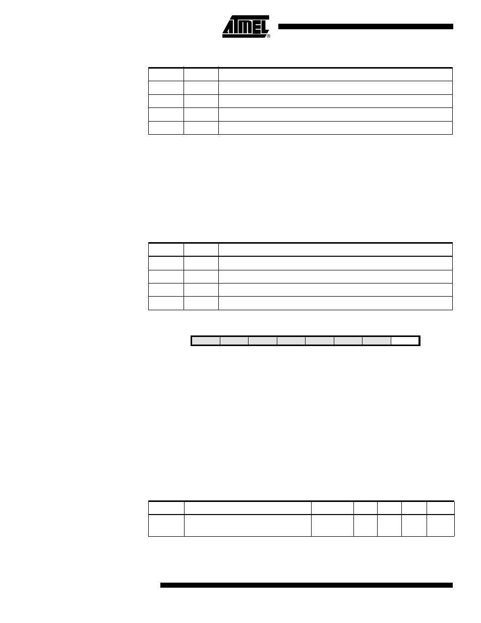
Extended MCU Control
Register – EMCUCR
• Bit 0 – ISC2: Interrupt Sense Control 2
The asynchronous External Interrupt 2 is activated by the external pin INT2 if the SREG
I-bit and the corresponding interrupt mask in GICR are set. If ISC2 is cleared (zero), a
falling edge on INT2 activates the interrupt. If ISC2 is set (one), a rising edge on INT2
activates the interrupt. Edges on INT2 are registered asynchronously. Pulses on INT2
wider than the minimum pulse width given in Table 45 will generate an interrupt. Shorter
pulses are not guaranteed to generate an interrupt. When changing the ISC2 bit, an
interrupt can occur. Therefore, it is recommended to first disable INT2 by clearing its
Interrupt Enable bit in the GICR Register. Then, the ISC2 bit can be changed. Finally,
the INT2 Interrupt Flag should be cleared by writing a logical one to its Interrupt Flag bit
(INTF2) in the GIFR Register before the interrupt is re-enabled.
Table 43. Interrupt 1 Sense Control
ISC11
ISC10
Description
0
0
The low level of INT1 generates an interrupt request.
0
1
Any logical change on INT1 generates an interrupt request.
1
0
The falling edge of INT1 generates an interrupt request.
1
1
The rising edge of INT1 generates an interrupt request.
Table 44. Interrupt 0 Sense Control
ISC01
ISC00
Description
0
0
The low level of INT0 generates an interrupt request.
0
1
Any logical change on INT0 generates an interrupt request.
1
0
The falling edge of INT0 generates an interrupt request.
1
1
The rising edge of INT0 generates an interrupt request.
Bit
7
6
5
4
3
2
1
0
SM0
SRL2
SRL1
SRL0
SRW01
SRW00
SRW11
ISC2
EMCUCR
Read/Write
R/W
R/W
R/W
R/W
R/W
R/W
R/W
R/W
Initial Value
0
0
0
0
0
0
0
0
Table 45. Asynchronous External Interrupt Characteristics
Symbol
Parameter
Condition
Min.
Typ.
Max.
Units
t
INT
Minimum pulse width for
asynchronous external interrupt
50
ns