Scanning the analog comparator, Atmega162/v – Rainbow Electronics ATmega162V User Manual
Page 211
211
ATmega162/V
2513E–AVR–09/03
Scanning the Analog
Comparator
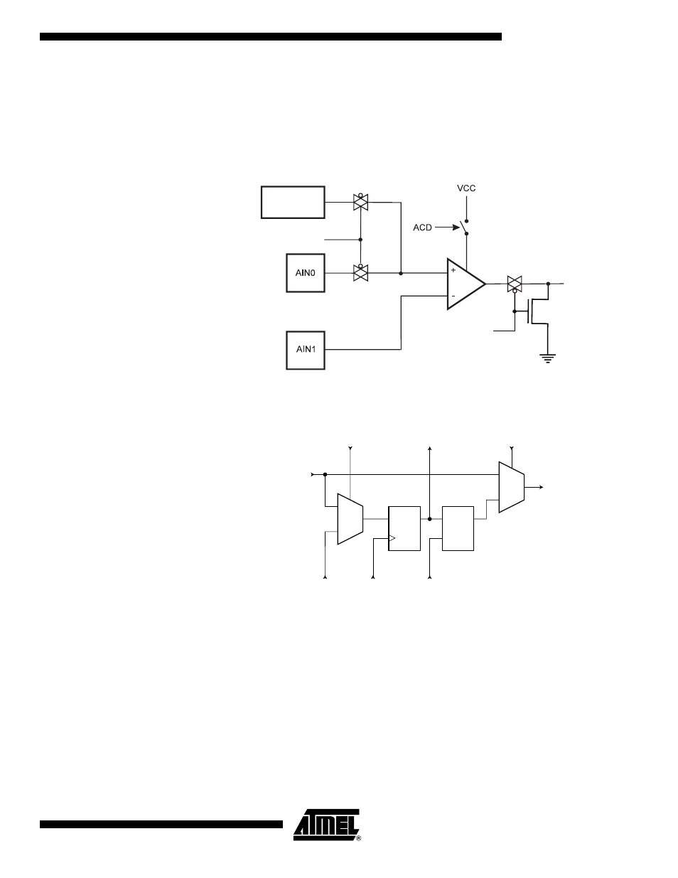
The relevant Comparator signals regarding Boundary-scan are shown in Figure 91. The
Boundary-scan cell from Figure 92 is attached to each of these signals. The signals are
described in Table 87.
The Comparator need not be used for pure connectivity testing, since all analog inputs
are shared with a digital port pin as well.
Figure 91. Analog Comparator
Figure 92. General Boundary-scan Cell used for Signals for Comparator
ACBG
BANDGAP
REFERENCE
AC_IDLE
ACO
0
1
D
Q
D
Q
G
0
1
From
Previous
Cell
ClockDR
UpdateDR
ShiftDR
To
Next
Cell
EXTEST
To Snalog Circuitry/
To Digital Logic
From Digital Logic/
From Analog Ciruitry
See also other documents in the category Rainbow Electronics Sensors:
- MAX5151 (16 pages)
- MAXQ3108 (64 pages)
- MAX5661 (39 pages)
- MAX6691 (7 pages)
- MAX5362 (12 pages)
- ADC10158 (26 pages)
- MAX8922L (14 pages)
- MAX8596Z (8 pages)
- MAX7491 (18 pages)
- MAX15040 (15 pages)
- MAX5177 (16 pages)
- ADC08138 (22 pages)
- MAX5961 (42 pages)
- T89C51RD2 (86 pages)
- MAX16055 (9 pages)
- MAX6659 (17 pages)
- ADC0820 (20 pages)
- MAX6678 (19 pages)
- MAX8884Z (15 pages)
- MAX16915 (9 pages)
- MAX8620 (18 pages)
- MAX5144 (12 pages)
- MAX6670 (8 pages)
- MAX8760 (39 pages)
- W78C32C (14 pages)
- MX7533 (8 pages)
- MAX8727 (13 pages)
- MAX9053 (15 pages)
- W78C54 (16 pages)
- MAX8614B (15 pages)
- W90N740 (219 pages)
- MAX6626 (13 pages)
- ADC10738 (30 pages)
- MAX17000 (31 pages)
- MAX5051 (21 pages)
- MAXQ1004 (18 pages)
- MAX6871 (51 pages)
- MX7847 (12 pages)
- MAX6608 (6 pages)
- MAX17083 (15 pages)
- MAX6641 (17 pages)
- MAX5251 (16 pages)
- MAX6338 (8 pages)
- MAX6690 (16 pages)
- MAX8668 (18 pages)