Usart control and status register c – ucsrc(1), Atmega162/v – Rainbow Electronics ATmega162V User Manual
Page 188
188
ATmega162/V
2513E–AVR–09/03
USART Control and Status
Register C – UCSRC
Note:
1. The UCSRC Register shares the same I/O location as the UBRRH Register. See the
“Accessing UBRRH/ UCSRC Registers” on page 183 section which describes how to
access this register.
• Bit 7 – URSEL: Register Select
This bit selects between accessing the UCSRC or the UBRRH Register. It is read as
one when reading UCSRC. The URSEL must be one when writing the UCSRC.
• Bit 6 – UMSEL: USART Mode Select
This bit selects between asynchronous and synchronous mode of operation.
• Bit 5:4 – UPM1:0: Parity Mode
These bits enable and set type of parity generation and check. If enabled, the transmit-
ter will automatically generate and send the parity of the transmitted data bits within
each frame. The receiver will generate a parity value for the incoming data and compare
it to the UPM0 setting. If a mismatch is detected, the UPE Flag in UCSRA will be set.
• Bit 3 – USBS: Stop Bit Select
This bit selects the number of stop bits to be inserted by the transmitter. The receiver
ignores this setting.
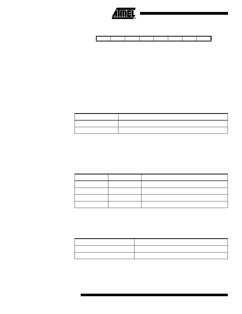
Bit
7
6
5
4
3
2
1
0
URSEL
UMSEL
UPM1
UPM0
USBS
UCSZ1
UCSZ0
UCPOL
UCSRC
Read/Write
R/W
R/W
R/W
R/W
R/W
R/W
R/W
R/W
Initial Value
1
0
0
0
0
1
1
0
Table 73. UMSEL Bit Settings
UMSEL
Mode
0
Asynchronous Operation
1
Synchronous Operation
Table 74. UPM Bits Settings
UPM1
UPM0
Parity Mode
0
0
Disabled
0
1
Reserved
1
0
Enabled, Even Parity
1
1
Enabled, Odd Parity
Table 75. USBS Bit Settings
USBS
Stop Bit(s)
0
1-bit
1
2-bit