External clock, Clock output buffer, Atmega162/v – Rainbow Electronics ATmega162V User Manual
Page 38
38
ATmega162/V
2513E–AVR–09/03
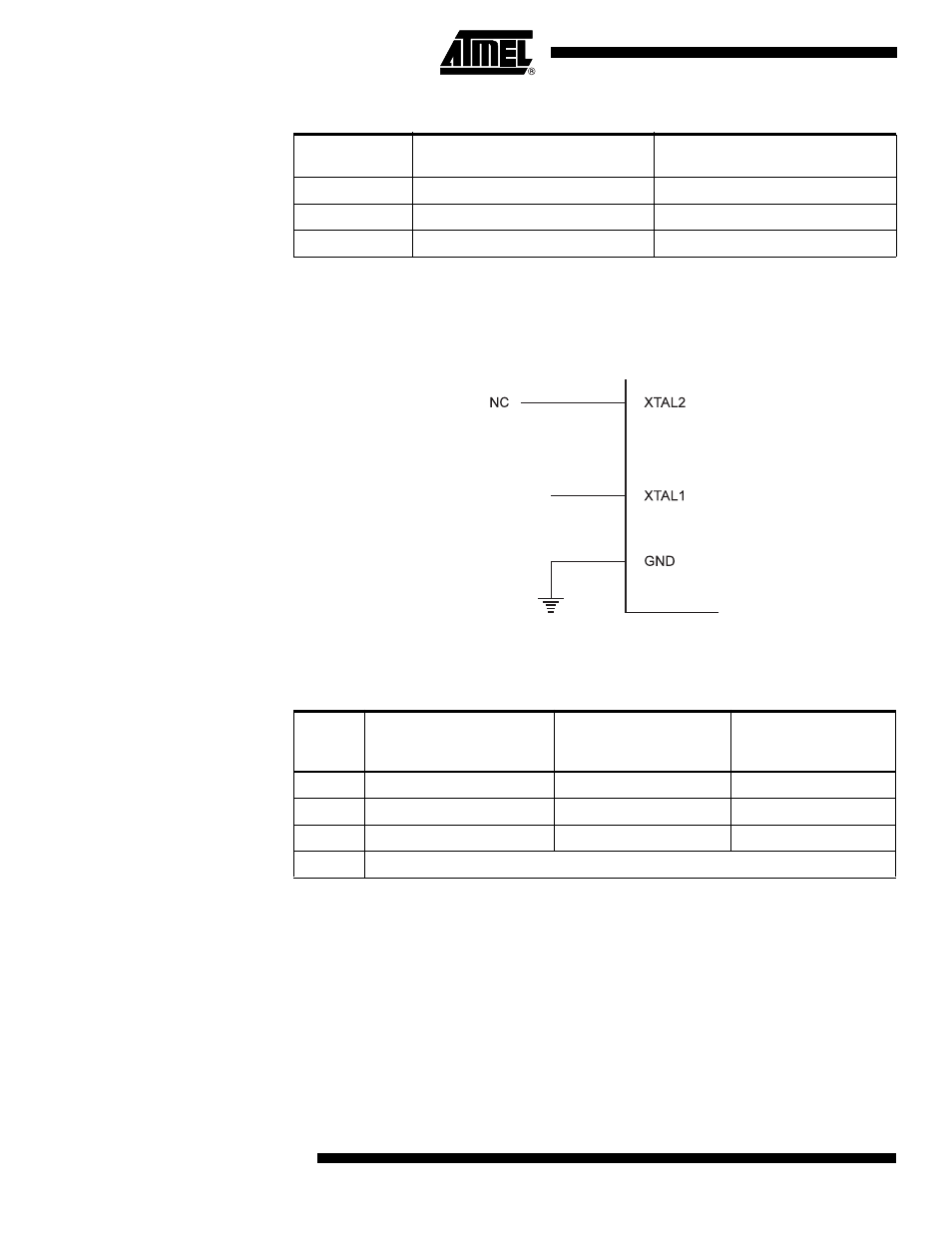
External Clock
To drive the device from an external clock source, XTAL1 should be driven as shown in
Figure 20. To run the device on an external clock, the CKSEL Fuses must be pro-
grammed to “0000”.
Figure 20. External Clock Drive Configuration
When this clock source is selected, start-up times are determined by the SUT Fuses as
shown in Table 14.
When applying an external clock, it is required to avoid sudden changes in the applied
clock frequency to ensure stable operation of the MCU. A variation in frequency of more
than 2% from one clock cycle to the next can lead to unpredictable behavior. It is
required to ensure that the MCU is kept in reset during such changes in the clock
frequency.
Note that the System Clock Prescaler can be used to implement run-time changes of
the internal clock frequency while still ensuring stable operation. Refer to “System Clock
Prescaler” on page 39 for details.
Clock output buffer
When the CKOUT Fuse is programmed, the system clock will be output on PortB 0. This
mode is suitable when chip clock is used to drive other circuits on the system. The clock
Table 13. Internal RC Oscillator Frequency Range.
OSCCAL Value
Min Frequency in Percentage of
Nominal Frequency
Max Frequency in Percentage of
Nominal Frequency
0x00
50%
100%
0x3F
75%
150%
0x7F
100%
200%
Table 14. Start-up Times for the External Clock Selection
SUT1..0
Start-up Time from
Power-down and
Power-save
Additional Delay from
Reset (V
CC
= 5.0V)
Recommended Usage
00
6 CK
–
BOD enabled
01
6 CK
4.1 ms
Fast rising power
10
6 CK
65 ms
Slowly rising power
11
Reserved
EXTERNAL
CLOCK
SIGNAL