Watchdog timer control register – wdtcr, Atmega162/v – Rainbow Electronics ATmega162V User Manual
Page 52
52
ATmega162/V
2513E–AVR–09/03
shown in Table 22. Safety level 0 corresponds to the setting in ATmega161. There is no
restriction on enabling the WDT in any of the safety levels. Refer to “Timed Sequences
for Changing the Configuration of the Watchdog Timer” on page 55 for details.
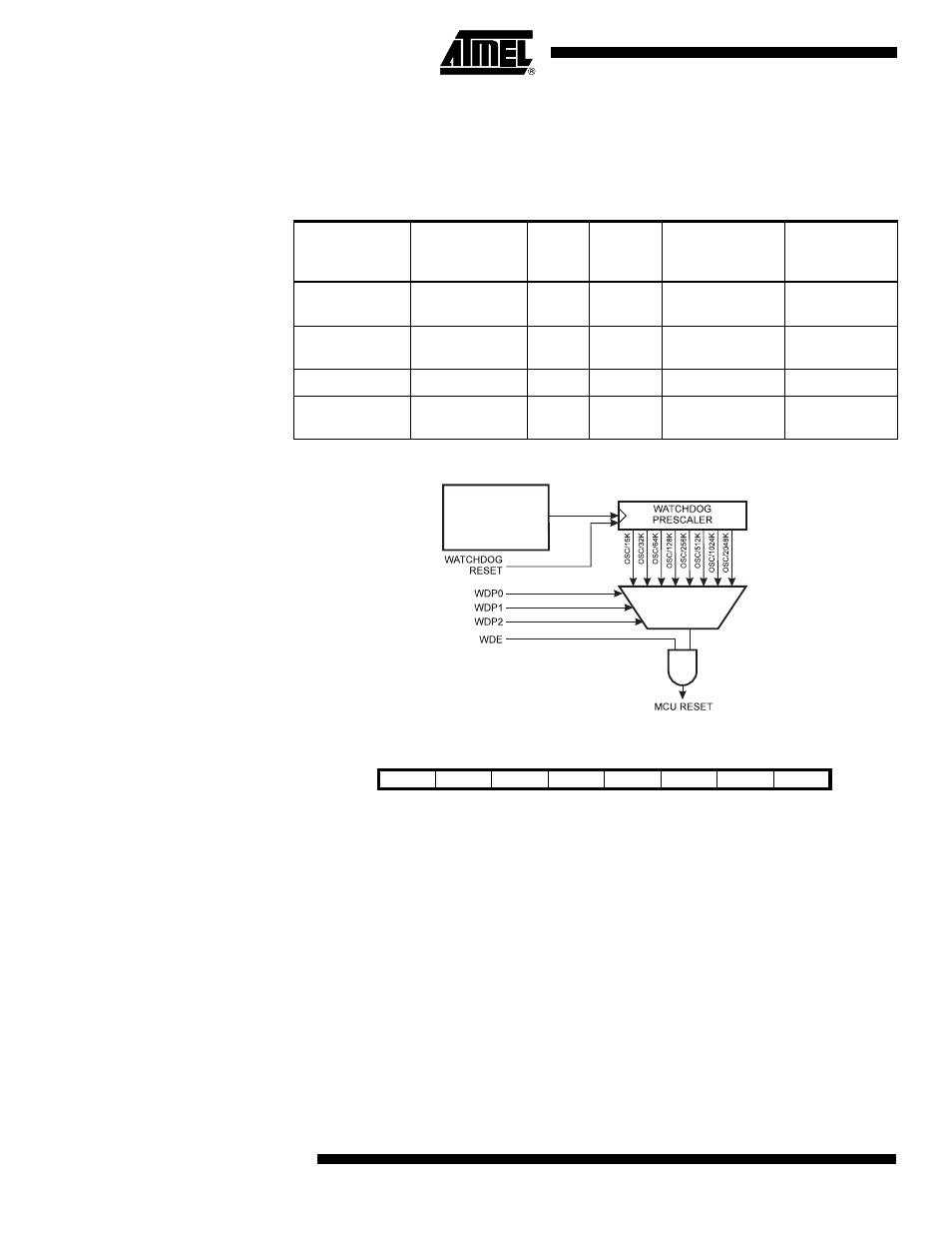
Figure 27. Watchdog Timer
Watchdog Timer Control
Register – WDTCR
• Bits 7..5 – Res: Reserved Bits
These bits are reserved bits in the ATmega162 and will always read as zero.
• Bit 4 – WDCE: Watchdog Change Enable
This bit must be set when the WDE bit is written to logic zero. Otherwise, the Watchdog
will not be disabled. Once written to one, hardware will clear this bit after four clock
cycles. Refer to the description of the WDE bit for a Watchdog disable procedure. In
Safety Levels 1 and 2, this bit must also be set when changing the prescaler bits. See
“Timed Sequences for Changing the Configuration of the Watchdog Timer” on page 55.
• Bit 3 – WDE: Watchdog Enable
When the WDE is written to logic one, the Watchdog Timer is enabled, and if the WDE is
written to logic zero, the Watchdog Timer function is disabled. WDE can only be cleared
Table 22. WDT Configuration as a Function of the Fuse Settings of M161C and
WDTON.
M161C
WDTON
Safety
Level
WDT
Initial
State
How to Disable
the WDT
How to
Change Time-
out
Unprogrammed
Unprogrammed
1
Disabled
Timed sequence
Timed
sequence
Unprogrammed
Programmed
2
Enabled
Always enabled
Timed
sequence
Programmed
Unprogrammed
0
Disabled
Timed sequence
No restriction
Programmed
Programmed
2
Enabled
Always enabled
Timed
sequence
WATCHDOG
OSCILLATOR
Bit
7
6
5
4
3
2
1
0
–
–
–
WDCE
WDE
WDP2
WDP1
WDP0
WDTCR
Read/Write
R
R
R
R/W
R/W
R/W
R/W
R/W
Initial Value
0
0
0
0
0
0
0
0