See table 90 and table 91, Atmega162/v – Rainbow Electronics ATmega162V User Manual
Page 219
219
ATmega162/V
2513E–AVR–09/03
ming of the Flash memory by SPM instruction. Similarly, the general Read/Write Lock
(Lock bit mode 1) does not control reading nor writing by LPM/SPM, if it is attempted.
Note:
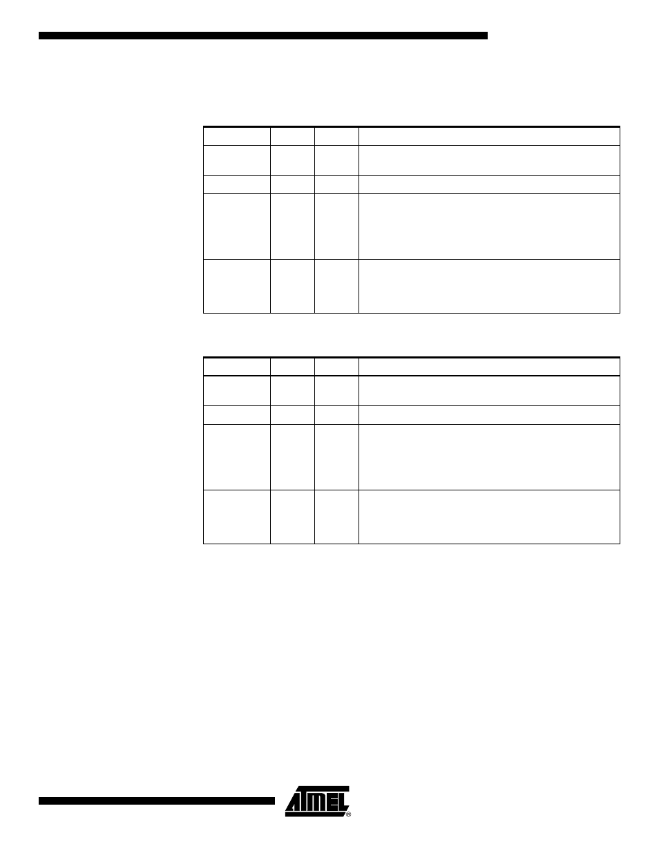
1. “1” means unprogrammed, “0” means programmed
Note:
1. “1” means unprogrammed, “0” means programmed
Table 90. Boot Lock Bit0 Protection Modes (Application Section)
BLB0 Mode
BLB02
BLB01
Protection
1
1
1
No restrictions for SPM or LPM accessing the Application
section.
2
1
0
SPM is not allowed to write to the Application section.
3
0
0
SPM is not allowed to write to the Application section, and
LPM executing from the Boot Loader section is not
allowed to read from the Application section. If Interrupt
Vectors are placed in the Boot Loader section, interrupts
are disabled while executing from the Application section.
4
0
1
LPM executing from the Boot Loader section is not
allowed to read from the Application section. If Interrupt
Vectors are placed in the Boot Loader section, interrupts
are disabled while executing from the Application section.
Table 91. Boot Lock Bit1 Protection Modes (Boot Loader Section)
BLB1 Mode
BLB12
BLB11
Protection
1
1
1
No restrictions for SPM or LPM accessing the Boot Loader
section.
2
1
0
SPM is not allowed to write to the Boot Loader section.
3
0
0
SPM is not allowed to write to the Boot Loader section,
and LPM executing from the Application section is not
allowed to read from the Boot Loader section. If Interrupt
Vectors are placed in the Application section, interrupts
are disabled while executing from the Boot Loader section.
4
0
1
LPM executing from the Application section is not allowed
to read from the Boot Loader section. If Interrupt Vectors
are placed in the Application section, interrupts are
disabled while executing from the Boot Loader section.