Extended mcu control register – emcucr, Idle mode, Power-down mode – Rainbow Electronics ATmega162V User Manual
Page 42: See table 16, Table 16, Atmega162/v
42
ATmega162/V
2513E–AVR–09/03
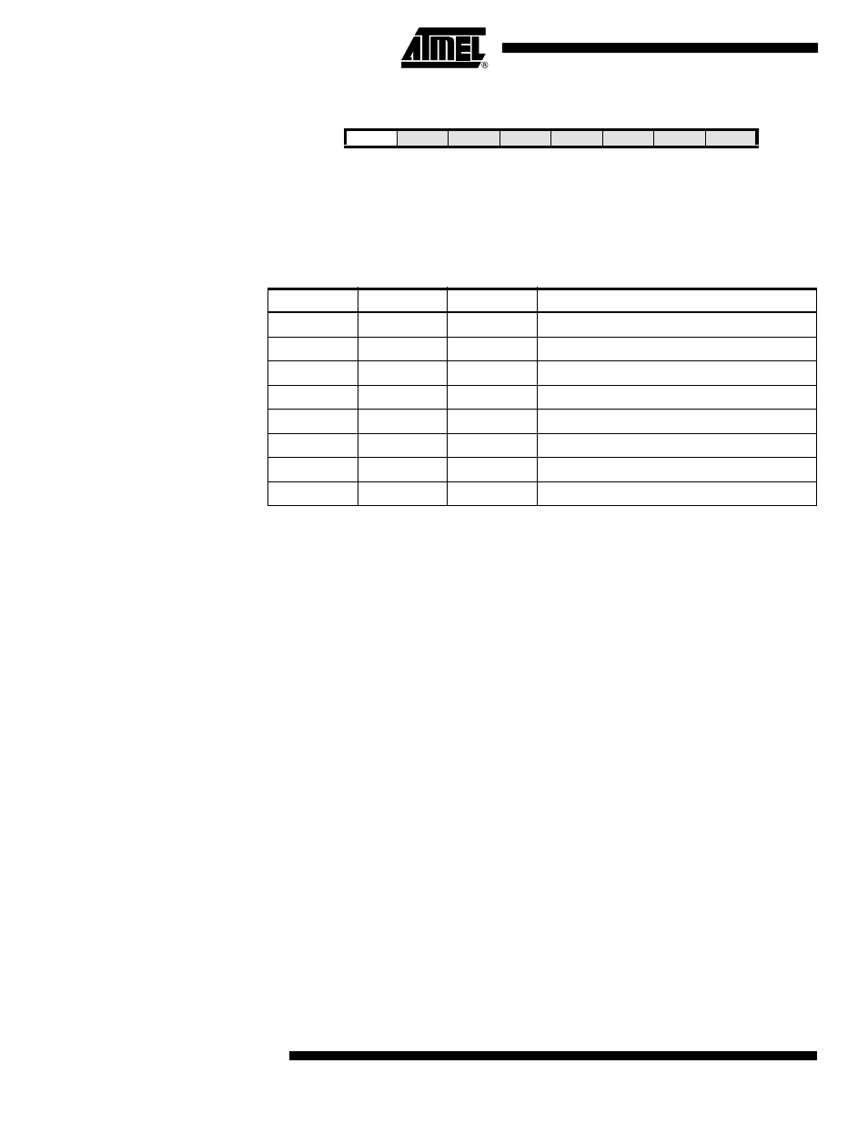
Extended MCU Control
Register – EMCUCR
• Bit 7 – SM0: Sleep Mode Select Bit 0
The Sleep Mode Select bits select between the five available sleep modes as shown in
Table 16.
Note:
1. Standby mode and Extended Standby mode are only available with external crystals
or resonators.
Idle Mode
When the SM2..0 bits are written to 000, the SLEEP instruction makes the MCU enter
Idle mode, stopping the CPU but allowing the SPI, USART, Analog Comparator,
Timer/Counters, Watchdog, and the interrupt system to continue operating. This sleep
mode basically halts clk
CPU
and clk
FLASH
, while allowing the other clocks to run.
Idle mode enables the MCU to wake up from external triggered interrupts as well as
internal ones like the Timer Overflow and USART Transmit Complete interrupts. If
wake-up from the Analog Comparator interrupt is not required, the Analog Comparator
can be powered down by setting the ACD bit in the Analog Comparator Control and Sta-
tus Register – ACSR. This will reduce power consumption in Idle mode.
Power-down Mode
When the SM2..0 bits are written to 010, the SLEEP instruction makes the MCU enter
Power-down mode. In this mode, the external Oscillator is stopped, while the external
interrupts and the Watchdog continue operating (if enabled). Only an External Reset, a
Watchdog Reset, a Brown-out Reset, an External Level Interrupt on INT0 or INT1, an
external interrupt on INT2, or a pin change interrupt can wake up the MCU. This sleep
mode basically halts all generated clocks, allowing operation of asynchronous modules
only.
Note that if a level triggered interrupt is used for wake-up from Power-down mode, the
changed level must be held for some time to wake up the MCU. Refer to “External Inter-
rupts” on page 83 for details.
When waking up from Power-down mode, there is a delay from the wake-up condition
occurs until the wake-up becomes effective. This allows the clock to restart and become
stable after having been stopped. The wake-up period is defined by the same CKSEL
Fuses that define the Reset Time-out period, as described in “Clock Sources” on page
34.
Bit
7
6
5
4
3
2
1
0
SM0
SRL2
SRL1
SRL0
SRW01
SRW00
SRW11
ISC2
EMCUCR
Read/Write
R/W
R/W
R/W
R/W
R/W
R/W
R/W
R/W
Initial Value
0
0
0
0
0
0
0
0
Table 16. Sleep Mode Select
SM2
SM1
SM0
Sleep Mode
0
0
0
Idle
0
0
1
Reserved
0
1
0
Power-down
0
1
1
Power-save
1
0
0
Reserved
1
0
1
Reserved
1
1
0
Standby
1
1
1
Extended Standby