Atmega162/v – Rainbow Electronics ATmega162V User Manual
Page 100
100
ATmega162/V
2513E–AVR–09/03
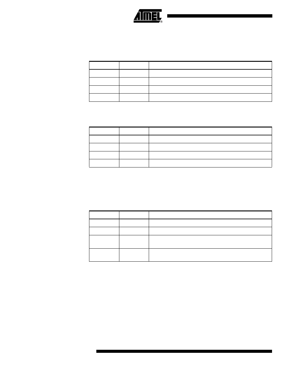
When OC0 is connected to the pin, the function of the COM01:0 bits depends on the
WGM01:0 bit setting. Table 48 shows the COM01:0 bit functionality when the WGM01:0
bits are set to a Normal or CTC mode (non-PWM).
Table 49 shows the COM01:0 bit functionality when the WGM01:0 bits are set to fast
PWM mode.
Note:
1. A special case occurs when OCR0 equals TOP and COM01 is set. In this case, the
Compare Match is ignored, but the set or clear is done at TOP. See “Fast PWM
Mode” on page 94 for more details.
Table 50 shows the COM01:0 bit functionality when the WGM01:0 bits are set to phase
correct PWM mode.
Note:
1. A special case occurs when OCR0 equals TOP and COM01 is set. In this case, the
Compare Match is ignored, but the set or clear is done at TOP. See “Phase Correct
PWM Mode” on page 96 for more details.
Table 48. Compare Output Mode, non-PWM Mode
COM01
COM00
Description
0
0
Normal port operation, OC0 disconnected.
0
1
Toggle OC0 on Compare Match.
1
0
Clear OC0 on Compare Match.
1
1
Set OC0 on Compare Match.
Table 49. Compare Output Mode, fast PWM Mode
COM01
COM00
Description
0
0
Normal port operation, OC0 disconnected.
0
1
Reserved
1
0
Clear OC0 on Compare Match, set OC0 at TOP.
1
1
Set OC0 on Compare Match, clear OC0 at TOP.
Table 50. Compare Output Mode, Phase Correct PWM Mode
COM01
COM00
Description
0
0
Normal port operation, OC0 disconnected.
0
1
Reserved
1
0
Clear OC0 on Compare Match when up-counting. Set OC0 on
Compare Match when down-counting.
1
1
Set OC0 on Compare Match when up-counting. Clear OC0 on
Compare Match when down-counting.