Usart baud rate registers – ubrrl and ubrrh(1), Atmega162/v – Rainbow Electronics ATmega162V User Manual
Page 189
189
ATmega162/V
2513E–AVR–09/03
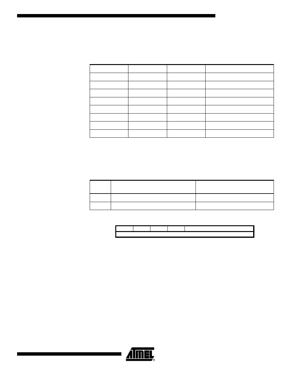
• Bit 2:1 – UCSZ1:0: Character Size
The UCSZ1:0 bits combined with the UCSZ2 bit in UCSRB sets the number of data bits
(Character Size) in a frame the receiver and transmitter use.
• Bit 0 – UCPOL: Clock Polarity
This bit is used for synchronous mode only. Write this bit to zero when asynchronous
mode is used. The UCPOL bit sets the relationship between data output change and
data input sample, and the synchronous clock (XCK).
USART Baud Rate Registers –
UBRRL and UBRRH
Note:
1. The UBRRH Register shares the same I/O location as the UCSRC Register. See the
“Accessing UBRRH/ UCSRC Registers” on page 183 section which describes how to
access this register.
• Bit 15 – URSEL: Register Select
This bit selects between accessing the UBRRH or the UCSRC Register. It is read as
zero when reading UBRRH. The URSEL must be zero when writing the UBRRH.
• Bit 14:12 – Reserved Bits
These bits are reserved for future use. For compatibility with future devices, these bit
must be written to zero when UBRRH is written.
Table 76. UCSZ Bits Settings
UCSZ2
UCSZ1
UCSZ0
Character Size
0
0
0
5-bit
0
0
1
6-bit
0
1
0
7-bit
0
1
1
8-bit
1
0
0
Reserved
1
0
1
Reserved
1
1
0
Reserved
1
1
1
9-bit
Table 77. UCPOL Bit Settings
UCPOL
Transmitted Data Changed
(Output of TxD Pin)
Received Data Sampled
(Input on RxD Pin)
0
Rising XCK Edge
Falling XCK Edge
1
Falling XCK Edge
Rising XCK Edge
Bit
15
14
13
12
11
10
9
8
URSEL
–
–
–
UBRR[11:8]
UBRRH
UBRR[7:0]
UBRRL
7
6
5
4
3
2
1
0
Read/Write
R/W
R
R
R
R/W
R/W
R/W
R/W
R/W
R/W
R/W
R/W
R/W
R/W
R/W
R/W
Initial Value
0
0
0
0
0
0
0
0
0
0
0
0
0
0
0
0