Port f, Port f input pins address - pinf – Rainbow Electronics ATmega103L User Manual
Page 91
ATmega603/103
91
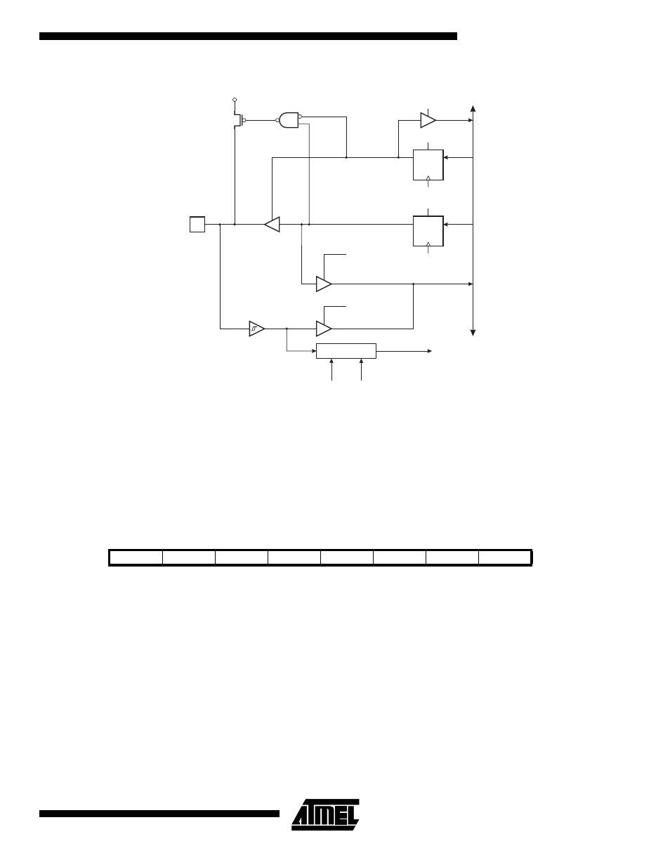
Figure 70. Port E Schematic Diagram (Pins PE4, PE5, PE6 and PE7)
Port F
Port F is an 8-bit input port.
One I/O memory location is allocated for Port F, the Port F Input Pins - PINF, $00 ($20).
All Port F pins are connected to the analog multiplexer which further is connected to the A/D converter. The digital input
function of Port F can be used together with the A/D converter, allowing the user to use some pins of Port F and digital
inputs and other as analog inputs, at the same time.
Port F Input Pins Address - PINF
The Port F Input Pins address - PINF - is not a register, and this address enables access to the physical value on each Port
F pin.
Bit
7
6
5
4
3
2
1
0
$00 ($20)
PINF7
PINF6
PINF5
PINF4
PINF3
PINF2
PINF1
PINF0
PINF
Read/Write
R
R
R
R
R
R
R
R
Initial value
Hi-Z
Hi-Z
Hi-Z
Hi-Z
Hi-Z
Hi-Z
Hi-Z
Hi-Z
DA
T
A
B
U
S
D
D
Q
Q
RESET
RESET
C
C
WD
WP
RD
MOS
PULL-
UP
PEn
R
R
WP:
WD:
RL:
RP:
RD:
n:
WRITE PORTE
WRITE DDRE
READ PORTE LATCH
READ PORTE PIN
READ DDRE
4, 5, 6, 7
DDEn
PORTEn
SENSE CONTROL
INTn
ISCn1
ISCn0
RL
RP