Rainbow Electronics ATmega103L User Manual
Page 104
ATmega603/103
104
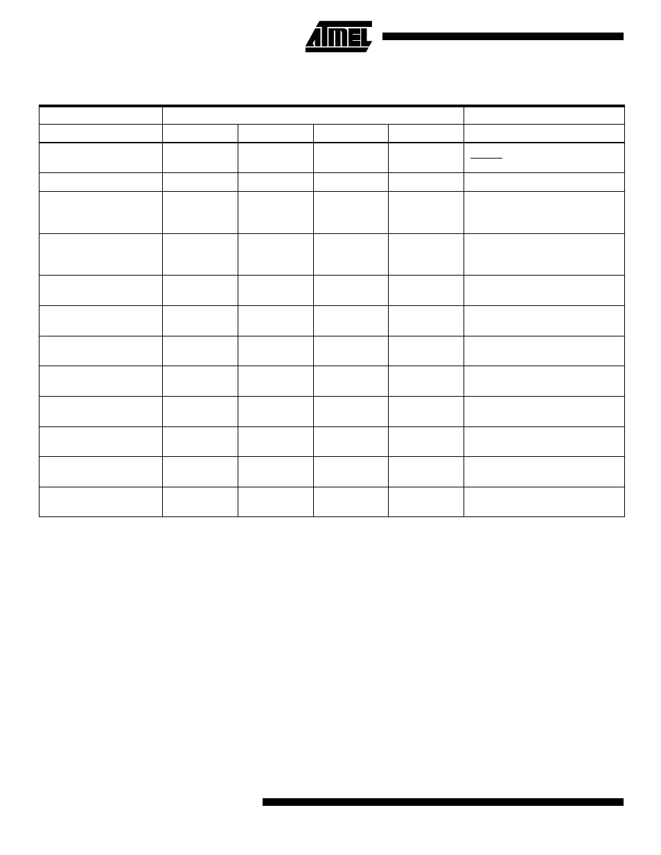
Note:
a = address high bits
b = address low bits
H = 0 - Low byte, 1 - High byte
o = data out
i = data in
x = don’t care
1 = Lock Bit 1
2 = Lock Bit 2
3 = SUT0 Fuse
4 = SUT1 Fuse
5 = SPIEN Fuse
6 = EESAVE Fuse
Table 45. Serial Programming Instruction Set
Instruction
Instruction Format
Operation
Byte 1
Byte 2
Byte 3
Byte 4
Programming Enable
1010 1100
0101 0011
xxxx xxxx
xxxx xxxx
Enable Serial Programming while
RESET is low.
Chip Erase
1010 1100
100x xxxx
xxxx xxxx
xxxx xxxx
Chip Erase EEPROM and Flash.
Read Program Memory
0010 H000
aaaa aaaa
bbbb bbbb
oooo oooo
Read H(high or low) data o from
Program memory at word address
a:b.
Load Program Memory
Page
0100 H000
xxxx xxxx
xbbb bbbb
iiii iiii
Write H (high or low) data i to
Program page memory at word
address b.
Write Program Memory
Page
0100 1100
aaaa aaaa
bxxx xxxx
xxxx xxxx
Write Program Memory Page at
address a:b.
Read EEPROM Memory
1010 0000
xxxx aaaa
bbbb bbbb
oooo oooo
Read data o from EEPROM
memory at address a:b.
Write EEPROM Memory
1100 0000
xxxx aaaa
bbbb bbbb
iiii iiii
Write data i to EEPROM memory
at address a:b.
Read Lock Bits
0101 1000
xxxx xxxx
xxxx xxxx
xxxx x
21x
Read Lock bits. ‘0’ = programmed,
‘1’ = unprogrammed.
Write Lock Bits
1010 1100
1111 1
211
xxxx xxxx
xxxx xxxx
Write Lock bits. Set bits
1,2 = ’0’ to
program Lock bits.
Read Fuse Bits
0101 0000
xxxx xxxx
xxxx xxxx
xx5x 6143
Read Fuse bits. ‘0’ = programmed,
‘1’ = unprogrammed.
Write Fuse Bits
1010 1100
1011 6143
xxxx xxxx
xxxx xxxx
Write Fuse bits. Set bit 6,4
,3 = ’0’
to program, ‘1’ to unprogram.
Read Signature Byte
0011 0000
xxxx xxxx
xxxx xxbb
oooo oooo
Read Signature Byte o at address
b.