Mcu status register - mcusr – Rainbow Electronics ATmega103L User Manual
Page 29
ATmega603/103
29
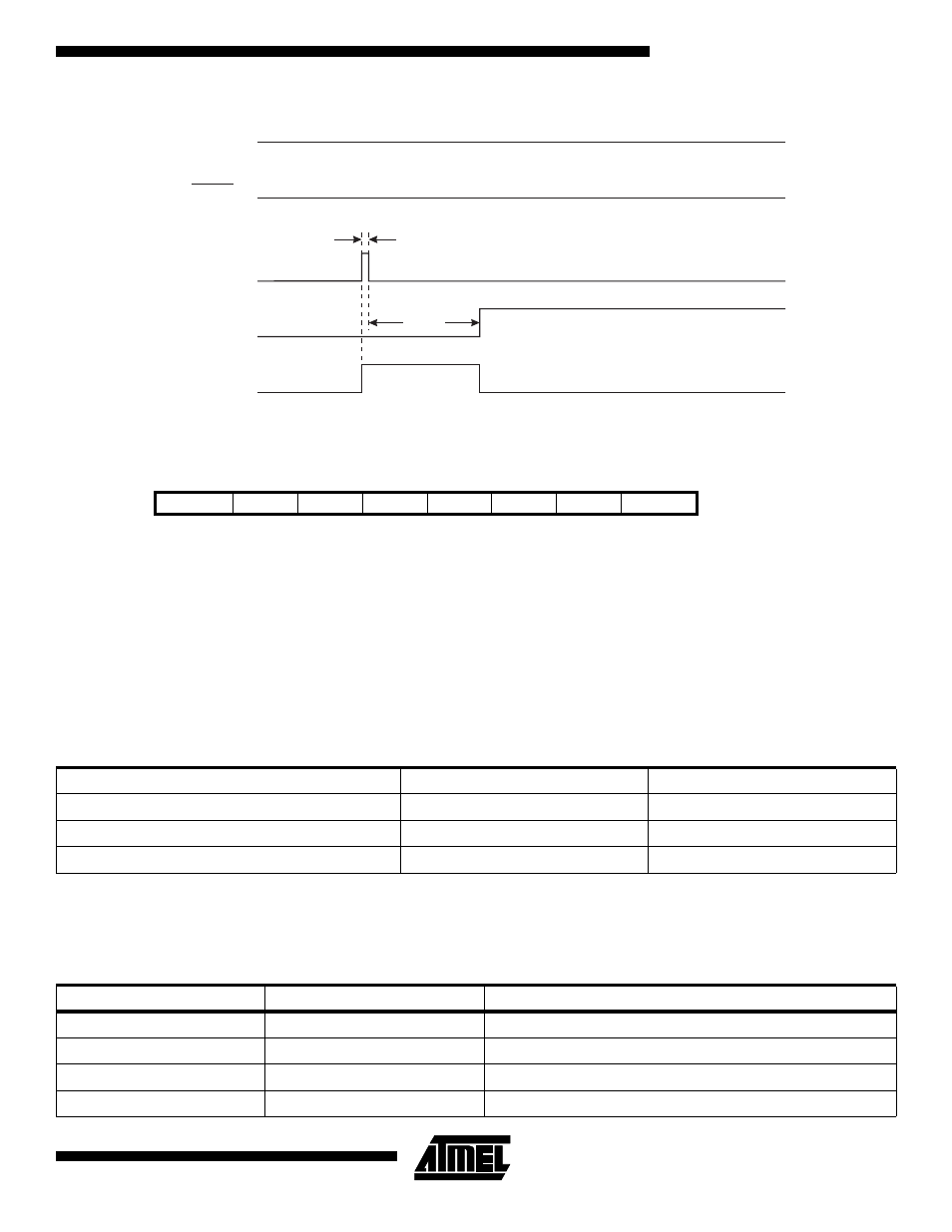
Figure 27. Watchdog Reset During Operation
MCU Status Register - MCUSR
The MCU Status Register provides information on which reset source caused an MCU reset.
•
Bits 7..2 - Res: Reserved Bits
These bits are reserved bits in the ATmega603/103 and always read as zero.
•
Bit 1 - EXTRF: External Reset Flag
After a power-on reset, this bit is undefined (X). It will be set by an external reset. A watchdog reset will leave this bit
unchanged.
•
Bit 0 - PORF: Power-on Reset Flag
This bit is set by a power-on reset. A watchdog reset or an external reset will leave this bit unchanged.
To summarize, the following table shows the value of these two bits after the three modes of reset:
To make use of these bits to identify a reset condition, the user software should clear both the PORF and EXTRF bits as
early as possible in the program. Checking the PORF and EXTRF values is done before the bits are cleared. If the bit is
cleared before an external or watchdog reset occurs, the source of reset can be found by using the following truth table:
Bit
7
6
5
4
3
2
1
0
$34 ($54)
-
-
-
-
-
-
EXTRF
PORF
MCUSR
Read/Write
R
R
R
R
R
R
R/W
R/W
Initial value
0
0
0
0
0
0
See bit description
Table 8. PORF and EXTRF Values after Reset
Reset Source
EXTRF
PORF
Power-on Reset
undefined
1
External Reset
1
unchanged
Watchdog Reset
unchanged
unchanged
Table 9. Reset Source Identification
EXTRF
PORF
Reset Source
0
0
Watchdog Reset
0
1
Power-on Reset
1
0
External Reset
1
1
Power-on Reset
VCC
RESET
RESET
TIME-OUT
INTERNAL
RESET
WDT
TIME-OUT
1 XTAL Cycle
t
TOUT