Prescaling – Rainbow Electronics ATmega103L User Manual
Page 68
ATmega603/103
68
Prescaling
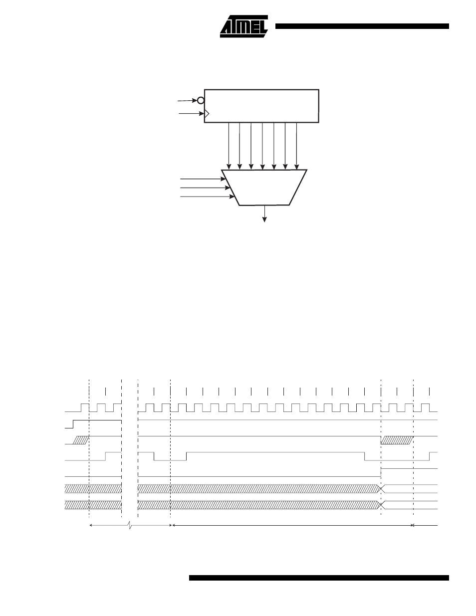
Figure 46. ADC Prescaler
The ADC contains a prescaler, which divides the system clock to an acceptable ADC clock frequency. The ADC accepts
input clock frequencies in the range 50 - 200 kHz. Applying a higher input frequency will result in a poorer accuracy, see
“ADC DC Characteristics” on page 72.
The ADPS0 - ADPS2 bits in ADCSR are used to generate a proper ADC clock input frequency from any XTAL frequency
above 100 kHz. The prescaler starts counting from the moment the ADC is switched on by setting the ADEN bit in ADCSR.
The prescaler keeps running for as long as the ADEN bit is set, and is continuously reset when ADEN is low.
When initiating a conversion by setting the ADSC bit in ADCSR, the conversion starts at the following falling edge of the
ADC clock cycle. The actual sample-and-hold takes place one ADC clock cycle after the start of the conversion. The result
is ready and written to the ADC Result Register after 13 cycles. The ADC needs 2 more clock cycles before a new conver-
sion can be started. If ADSC is set high in this period, the ADC will start the new conversion immediately. For a summary of
conversion times, see Table 27.
Figure 47. ADC timing diagram, first conversion
7-BIT ADC PRESCALER
ADC CLOCK SOURCE
CK
ADPS0
ADPS1
ADPS2
CK/128
CK/2
CK/4
CK/8
CK/16
CK/32
CK/64
Reset
ADEN
MSB of result
LSB of result
ADC clock
ADSC
Hold strobe
ADIF
ADCH
ADCL
Cycle number
ADEN
1
2
12
13
14
15
16
17
18
19
20
21
22
23
24
25
26
27
28
1
2
Dummy Conversion
Actual Conversion
Second
Conversion