Adc noise canceler function, Adc multiplexer select register - admux – Rainbow Electronics ATmega103L User Manual
Page 69
ATmega603/103
69
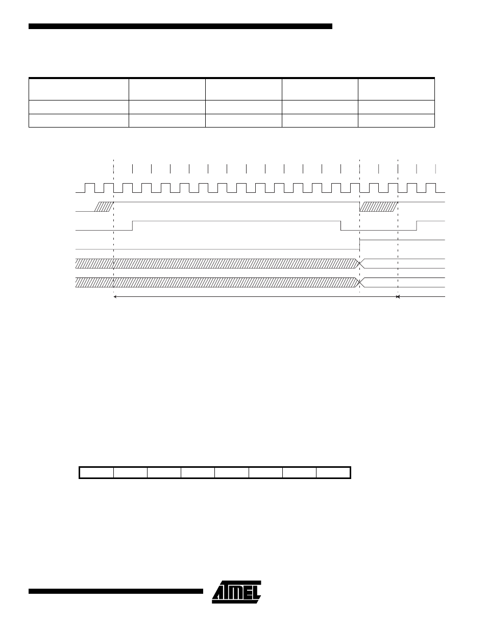
Figure 48. ADC Timing Diagram
ADC Noise Canceler Function
The ADC features a noise canceler that enables conversion during idle mode to reduce noise induced from the CPU core.
To make use of this feature, the following procedure should be used:
1.
Turn off the ADC by clearing ADEN.
2.
Turn on the ADC and simultaneously start a conversion by setting ADEN and ADSC. This starts a dummy
conversion that will be followed by a valid conversion.
3.
Within 14 ADC clock cycles, enter idle mode.
4.
If no other interrupts occur before the ADC conversion completes, the ADC interrupt will wake up the MCU and
execute the ADC conversion complete interrupt routine.
ADC Multiplexer Select Register - ADMUX
•
Bits 7..3 - Res: Reserved Bits
These bits are reserved bits in the ATmega603/103 and always read as zero.
•
Bits 2..0 - MUX2..MUX0: Analog Channel Select Bits 2-0
The value of these three bits selects which analog input 7-0 is connected to the ADC.
Table 27. ADC Conversion Time
Condition
Sample Cycle
Number
Result Ready
(cycle number)
Total Conversion
Time (cycles)
Total Conversion
Time (
µ
s)
1st Conversion
14
26
28
140 - 560
Single Conversion
1
13
15
75 - 300
Bit
7
6
5
4
3
2
1
0
$07 ($27)
-
-
-
-
-
MUX2
MUX1
MUX0
ADMUX
Read/Write
R
R
R
R
R
R/W
R/W
R/W
Initial value
0
0
0
0
0
0
0
0
1
2
3
4
5
6
7
8
9
10
11
12
13
MSB of result
LSB of result
ADC clock
ADSC
Hold strobe
ADIF
ADCH
ADCL
Cycle number
14
15
1
2
One Conversion
Next Conversion