Rainbow Electronics ATmega103L User Manual
Page 60
ATmega603/103
60
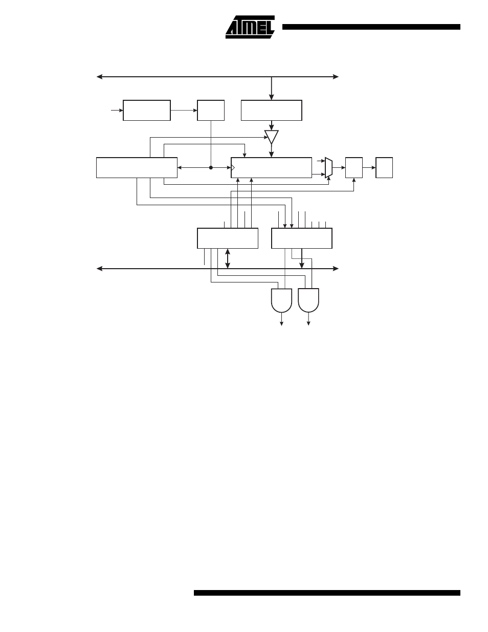
Figure 41. UART Transmitter
On the Baud Rate clock following the transfer operation to the shift register, the start bit is shifted out on the TXD pin, fol-
lowed by the data, LSB first. When the stop bit has been shifted out, the shift register is loaded if any new data has been
written to the UDR during the transmission. During loading, UDRE is set. If there is no new data in the UDR register to send
when the stop bit is shifted out, the UDRE flag will remain set. In this case, after the stop bit has been present on TXD for
one bit length, the TX Complete Flag, TXC, in USR is set.
The TXEN bit in UCR enables the UART transmitter when set (one). When this bit is cleared (zero), the PE1 pin can be
used for general I/O. When TXEN is set, the UART Transmitter will be connected to PE1, which is forced to be an output
pin regardless of the setting of the DDE1 bit in DDRE.
DATA BUS
DATA BUS
UART I/O DATA
REGISTER (UDR)
10(11)-BIT TX
SHIFT REGISTER
UART CONTROL
REGISTER (UCR)
CONTROL LOGIC
UART STATUS
REGISTER (USR)
BAUD RATE
GENERATOR
XTAL
TXB8
RXB8
TXEN
CHR9
RXEN
TXC
TXC
TXCIE
RXCIE
UDRIE
UDRE
RXC
FE
OR
UDRE
/16
UDRE
IRQ
TXC
IRQ
SHIFT ENABLE
STORE UDR
1
IDLE
BAUD
BAUD x 16
PIN CONTROL
LOGIC
TXD