Rainbow Electronics ATmega103L User Manual
Page 26
ATmega603/103
26
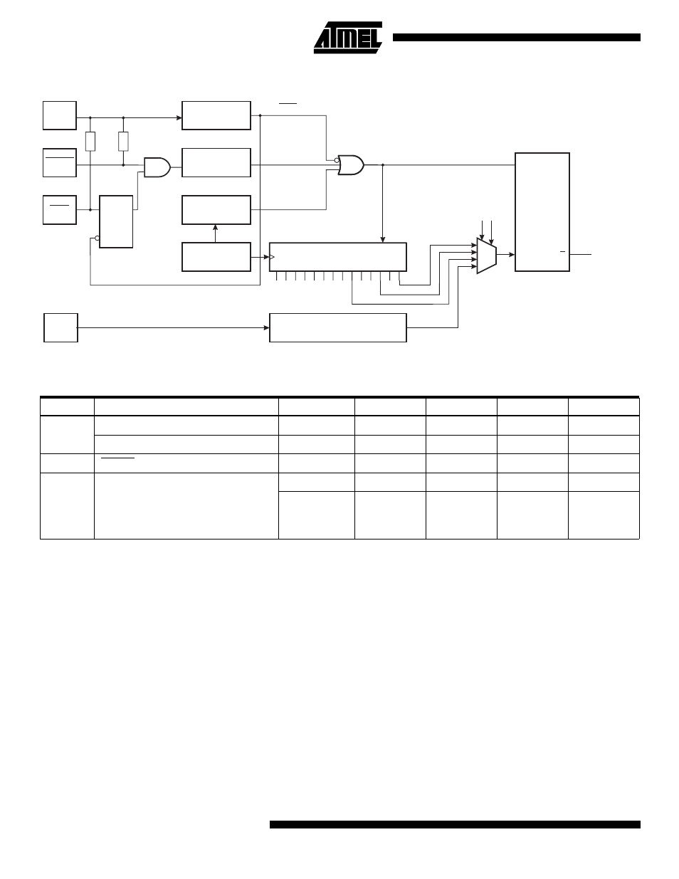
Figure 23. Reset Logic
Note:
1. The Power-On Reset will not work unless the supply voltage has been below V
POT
(falling)
Table 6. Reset Characteristics (V
CC
= 5V)
Symbol
Parameter
Condition
Min
Typ
Max
Units
V
POT
(1)
Power-On Reset Threshold (rising)
1.0
1.4
1.8
V
Power-On Reset Threshold (falling)
0.4
0.6
0.8
V
V
RST
RESET Pin Threshold Voltage
V
CC
/2
V
T
TOUT
Reset Delay Time-Out Period
SUT = 00
5
CPU cycles
SUT = 01
SUT = 10
SUT = 11
0.4
3.2
12.8
0.5
4.0
16.0
0.6
4.8
19.2
ms
Power-On Reset
Circuit
Reset Circuit
Watchdog
Timer
On-Chip
RC-Oscillator
14-Stage Ripple Counter
Delay Unit
Q
Q
S
R
INTERNAL
RESET
POR
VCC
XTAL1
RESET
PEN
D
Q
E
100-500K
10-50K
COUNTER RESET
SUT0
SUT1
Q8
Q11 Q13
See also other documents in the category Rainbow Electronics Sensors:
- MAX5151 (16 pages)
- MAXQ3108 (64 pages)
- MAX5661 (39 pages)
- MAX6691 (7 pages)
- MAX5362 (12 pages)
- ADC10158 (26 pages)
- MAX8922L (14 pages)
- MAX8596Z (8 pages)
- MAX7491 (18 pages)
- MAX15040 (15 pages)
- MAX5177 (16 pages)
- ADC08138 (22 pages)
- MAX5961 (42 pages)
- T89C51RD2 (86 pages)
- MAX16055 (9 pages)
- MAX6659 (17 pages)
- ADC0820 (20 pages)
- MAX6678 (19 pages)
- MAX8884Z (15 pages)
- MAX16915 (9 pages)
- MAX8620 (18 pages)
- MAX5144 (12 pages)
- MAX6670 (8 pages)
- MAX8760 (39 pages)
- W78C32C (14 pages)
- MX7533 (8 pages)
- MAX8727 (13 pages)
- MAX9053 (15 pages)
- W78C54 (16 pages)
- MAX8614B (15 pages)
- W90N740 (219 pages)
- MAX6626 (13 pages)
- ADC10738 (30 pages)
- MAX17000 (31 pages)
- MAX5051 (21 pages)
- MAXQ1004 (18 pages)
- MAX6871 (51 pages)
- MX7847 (12 pages)
- MAX6608 (6 pages)
- MAX17083 (15 pages)
- MAX6641 (17 pages)
- MAX5251 (16 pages)
- MAX6338 (8 pages)
- MAX6690 (16 pages)
- MAX8668 (18 pages)