Rainbow Electronics DS21458 User Manual
Page 75
DS21455/DS21458 Quad T1/E1/J1 Transceivers
75 of 270
Register Name:
IMR3
Register Description:
Interrupt Mask Register 3
Register Address:
1Bh
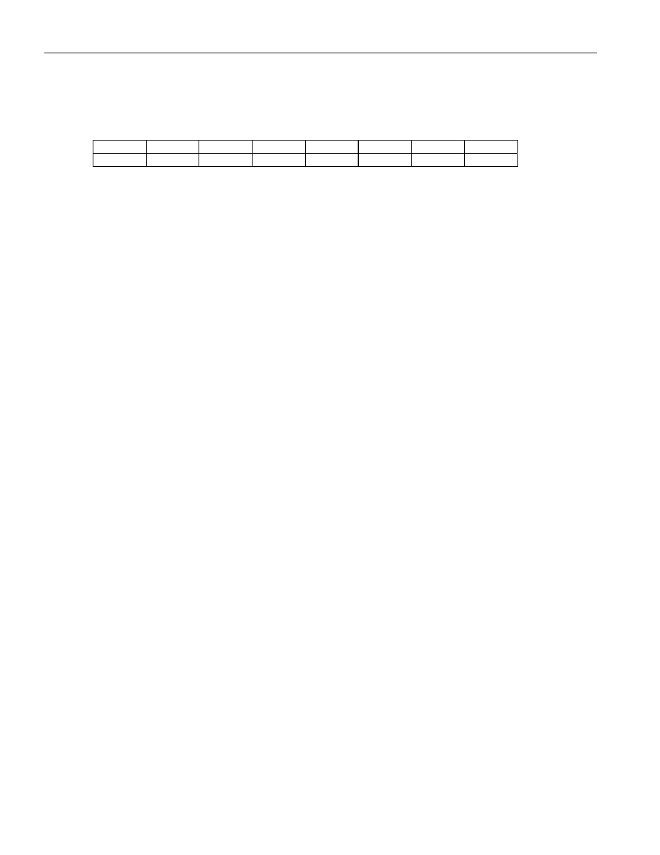
Bit
# 7 6 5 4 3 2 1 0
Name LSPARE
LDN LUP LOTC LORC
V52LNK
RDMA RRA
Default
0 0 0 0 0 0 0 0
Bit 0/Receive Remote Alarm Condition (RRA).
0 = interrupt masked
1 = interrupt enabled—interrupts on rising and falling edges
Bit 1/Receive Distant MF Alarm Condition (RDMA).
0 = interrupt masked
1 = interrupt enabled—interrupts on rising and falling edges
Bit 2/V5.2 Link Detected Condition (V52LNK).
0 = interrupt masked
1 = interrupt enabled—interrupts on rising and falling edges
Bit 3/Loss of Receive Clock Condition (LORC).
0 = interrupt masked
1 = interrupt enabled—interrupts on rising and falling edges
Bit 4/Loss of Transmit Clock Condition (LOTC).
0 = interrupt masked
1 = interrupt enabled—interrupts on rising and falling edges
Bit 5/Loop-Up Code Detected Condition (LUP).
0 = interrupt masked
1 = interrupt enabled—interrupts on rising and falling edges
Bit 6/Loop-Down Code Detected Condition (LDN).
0 = interrupt masked
1 = interrupt enabled–interrupts on rising and falling edges
Bit 7/Spare Code Detected Condition (LSPARE).
0 = interrupt masked
1 = interrupt enabled–interrupts on rising and falling edges