Hdlc mapping, Receive, 3 hdlc m – Rainbow Electronics DS21458 User Manual
Page 146: Apping, 3 hdlc mapping
DS21455/DS21458 Quad T1/E1/J1 Transceivers
146 of 270
24.3 HDLC Mapping
24.3.1 Receive
The HDLC controllers need to be assigned a space in the T1/E1 bandwidth in which they will transmit
and receive data. The controllers can be mapped to either the FDL (T1), Sa bits (E1), or to channels. If
mapped to channels, then any channel or combination of channels, contiguous or not, can be assigned to
an HDLC controller. When assigned to a channel(s) any combination of bits within the channel(s) can be
avoided.
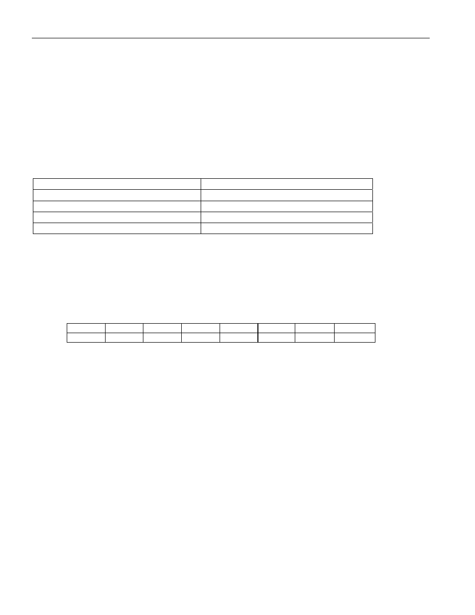
The HxRCS1–HxRCS4 registers are used to assign the receive controllers to channels 1–24 (T1) or
1–32 (E1) according to the following table.
REGISTER CHANNELS
HxRCS1 1–8
HxRCS2 9–16
HxRCS3 17–24
HxRCS4 25–32
Register Name:
H1RCS1, H1RCS2, H1RCS3, H1RCS4
H2RCS1, H2RCS2, H2RCS3, H2RCS4
Register Description:
HDLC # 1 Receive Channel Select x
HDLC # 2 Receive Channel Select x
Register Address:
92h, 93h, 94h, 95h
A2h, A3h, A4h, A5h
Bit
# 7 6 5 4 3 2 1 0
Name RHCS7 RHCS6 RHCS5 RHCS4 RHCS3 RHCS2 RHCS1 RHCS0
Default
0 0 0 0 0 0 0 0
Bit 0/Receive HDLC Channel Select Bit 0 (RHCS0). Select Channel 1, 9, 17, or 25.
Bit 1/Receive HDLC Channel Select Bit 1 (RHCS1). Select Channel 2, 10, 18, or 26.
Bit 2/Receive HDLC Channel Select Bit 2 (RHCS2). Select Channel 3, 11, 19, or 27.
Bit 3/Receive HDLC Channel Select Bit 3 (RHCS3). Select Channel 4, 12, 20, or 28.
Bit 4/Receive HDLC Channel Select Bit 4 (RHCS4). Select Channel 5, 13, 21, or 29.
Bit 5/Receive HDLC Channel Select Bit 5 (RHCS5). Select Channel 6, 14, 22, or 30.
Bit 6/Receive HDLC Channel Select Bit 6 (RHCS6). Select Channel 7, 15, 23, or 31.
Bit 7/Receive HDLC Channel Select Bit 7 (RHCS7). Select Channel 8, 16, 24, or 32.