Rainbow Electronics DS21458 User Manual
Page 174
DS21455/DS21458 Quad T1/E1/J1 Transceivers
174 of 270
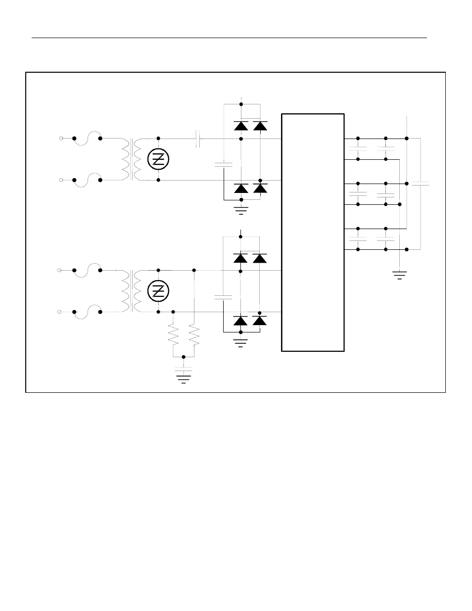
Figure 25-6. Protected Interface Using Internal Receive Termination
NOTES:
1) All resistor values are ±1%.
2) X1 and X2 are very low DCR transformers
3) C1 = 1µF ceramic.
4) S1 and S2 are 6V transient suppressers.
5) D1 to D8 are Schottky diodes.
6) The fuses, F1–F4, are optional to prevent AC power-line crosses from compromising the
transformers.
7)
The 68
mF is used to keep the local power-plane potential within tolerance during a surge.
TTIP
TRING
RTIP
RRING
DVDD
TVDD
RVDD
V
DD
V
DD
DVSS
TVSS
RVSS
DS21455/458
68
mF
2:1
1:1
D1 D2
D3
D4
C1
F1
F2
F3
F4
S1
0.1
mF
0.1
mF
0.1
mF
0.01
mF
X1
X2
TRANSMIT
LINE
RECEIVE
LINE
0.1
mF
10
mF
10
mF
+
+
+
0.1
mF
S2
60
W
60
W
V
DD
D5
D6
D7
D8
0.1
mF
- MAX12005 (14 pages)
- MAX7058 (14 pages)
- MAX9995 (13 pages)
- MAX7034 (13 pages)
- MAX7033 (16 pages)
- MAX9476 (8 pages)
- MAX9486 (8 pages)
- MAX14821 (29 pages)
- MAX9489 (11 pages)
- MAX9491 (11 pages)
- DS2130Q (22 pages)
- DS3131 (174 pages)
- DS26502 (125 pages)
- DS2153Q (48 pages)
- DS26503 (123 pages)
- DS2186 (11 pages)
- DS1842A (6 pages)
- DS3134 (203 pages)
- DS1876 (69 pages)
- DS1874 (88 pages)
- DS31256 (181 pages)
- DS2141A (35 pages)
- DS3184 (13 pages)
- DS2154 (69 pages)
- DS26504 (128 pages)
- DS3164 (12 pages)
- DS1852 (25 pages)
- DS2181A (32 pages)
- DS2151Q (46 pages)
- DS1843 (8 pages)
- DS2165Q (17 pages)
- DS3170 (233 pages)
- DS2180A (36 pages)
- DS2172 (20 pages)
- DS2152 (79 pages)
- DS1841 (16 pages)
- DS2182A (22 pages)
- DS2143Q (40 pages)
- DS2132A_Q (17 pages)
- DS1862 (42 pages)
- DS26519 (310 pages)
- DS2188 (11 pages)
- DS1875 (92 pages)
- DS33M33 (20 pages)