Rainbow Electronics DS21458 User Manual
Page 106
DS21455/DS21458 Quad T1/E1/J1 Transceivers
106 of 270
17.2.3 Software Signaling Insertion Enable Registers, T1 Mode
In T1 mode, only registers SSIE1 through SSIE3 are used since there are only 24 channels in a T1 frame.
Register Name:
SSIE1
Register Description:
Software Signaling Insertion Enable 1
Register Address:
08h
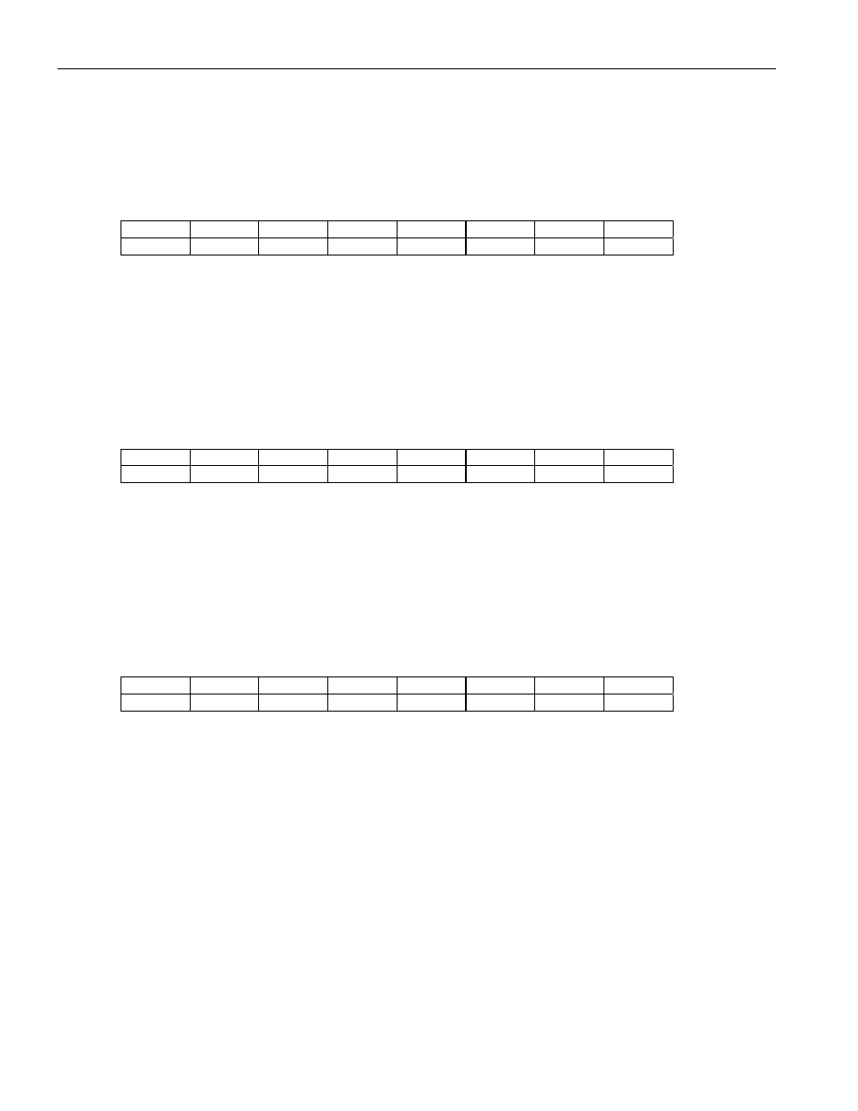
Bit
# 7 6 5 4 3 2 1 0
Name CH8 CH7 CH6 CH5 CH4 CH3 CH2 CH1
Default
0 0 0 0 0 0 0 0
Bits 0 to 7/Software Signaling Insertion Enable for and Channels 1 to 8 (CH1 to CH8). These bits determine what
channels are to have signaling inserted form the transmit signaling registers.
0 = do not source signaling data from the TSx registers for this channel
1 = source signaling data from the TSx registers for this channel
Register Name:
SSIE2
Register Description:
Software Signaling Insertion Enable 2
Register Address:
09h
Bit
# 7 6 5 4 3 2 1 0
Name CH16 CH15 CH14 CH13 CH12 CH11 CH10 CH9
Default
0 0 0 0 0 0 0 0
Bits 0 to 7/Software Signaling Insertion Enable for Channels 9 to 16 (CH9 to CH16). These bits determine what channels
are to have signaling inserted form the transmit signaling registers.
0 = do not source signaling data from the TSx registers for this channel
1 = source signaling data from the TSx registers for this channel
Register Name:
SSIE3
Register Description:
Software Signaling Insertion Enable 3
Register Address:
0Ah
Bit
# 7 6 5 4 3 2 1 0
Name CH24 CH23 CH22 CH21 CH20 CH19 CH18 CH17
Default
0 0 0 0 0 0 0 0
Bits 0 to 7/Software Signaling Insertion Enable for and Channels 17 to 24 (CH17 to CH24). These bits determine what
channels are to have signaling inserted form the transmit signaling registers.
0 = do not source signaling data from the TSx registers for this channel
1 = source signaling data from the TSx registers for this channel