Bert error counter, 4 bert e, Rror – Rainbow Electronics DS21458 User Manual
Page 194: Ounter, 4 bert error counter
DS21455/DS21458 Quad T1/E1/J1 Transceivers
194 of 270
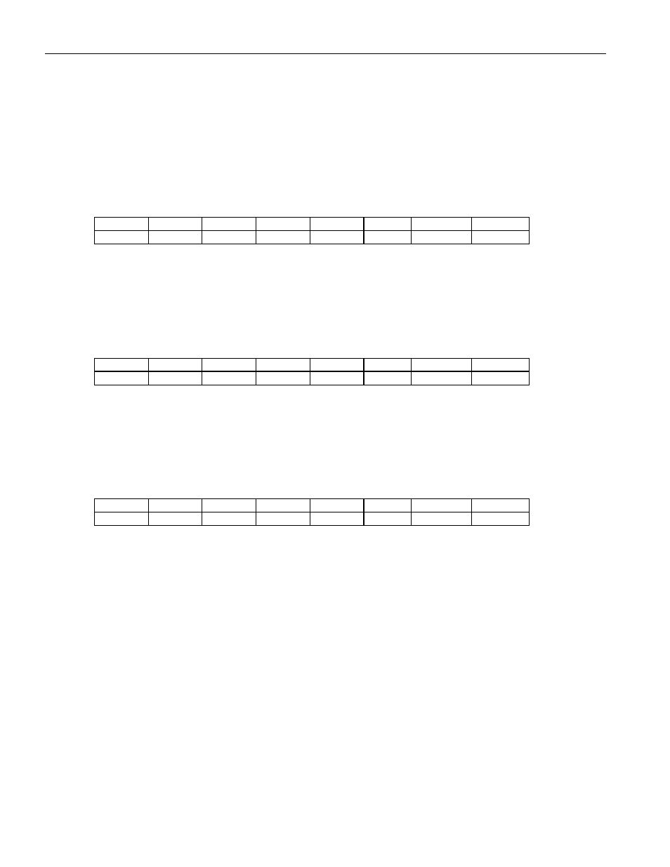
27.4 BERT Error Counter
Once the BERT has achieved synchronization, this 24-bit counter will increment for each data bit
received in error. Toggling the LC control bit in BC1 can clear this counter. This counter saturates when
full and will set the BECO status bit.
Register Name:
BEC1
Register Description:
BERT Error Count Register 1
Register Address:
E7h
Bit
# 7 6 5 4 3 2 1 0
Name EC7 EC6 EC5 EC4 EC3 EC2 EC1 EC0
Default
0 0 0 0 0 0 0 0
Bits 0 to 7/Error Counter Bits 0 to 7 (EC0 to EC7). EC0 is the LSB of the 24-bit counter.
Register Name:
BEC2
Register Description:
BERT Error Count Register 2
Register Address:
E8h
Bit
# 7 6 5 4 3 2 1 0
Name EC15 EC14 EC13 EC12 EC11 EC10 EC9 EC8
Default
0 0 0 0 0 0 0 0
Bits 0 to 7/Error Counter Bits 8 to 15 (EC8 to EC15).
Register Name:
BEC3
Register Description:
BERT Error Count Register 3
Register Address:
E9h
Bit
# 7 6 5 4 3 2 1 0
Name EC23 EC22 EC21 EC20 EC19 EC18 EC17 EC16
Default
0 0 0 0 0 0 0 0
Bits 0 to 7/Error Counter Bits 16 to 23 (EC16 to EC23). EC23 is the MSB of the 24-bit counter.