User-programmable output pins – Rainbow Electronics DS21458 User Manual
Page 210
DS21455/DS21458 Quad T1/E1/J1 Transceivers
210 of 270
33. USER-PROGRAMMABLE OUTPUT PINS
The DS21455/DS21458 provide four user-programmable output pins. The pins are automatically cleared
to zero at power-up or as a reset of a hardware- or software-issued reset.
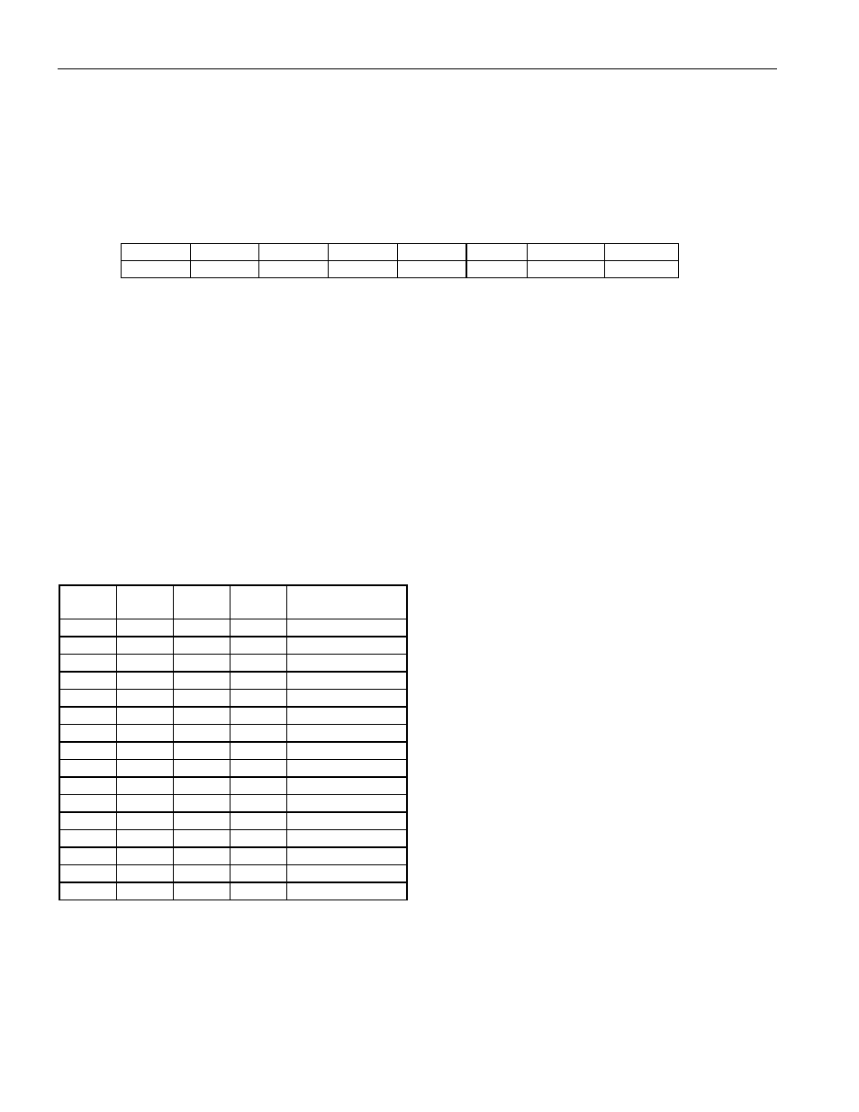
Register Name:
CCR4
Register Description:
Common Control Register 4
Register Address:
73h
Bit
# 7 6 5 4 3 2 1 0
Name RLT3 RLT2 RLT1 RLT0 UOP3 UOP2 UOP1 UOP0
Default
0 0 0 0 0 0 0 0
Bit 0/User-Defined Output 0 (UOP0).
0 = logic 0 level at pin
1 = logic 1 level at pin
Bit 1/User-Defined Output 1 (UOP1).
0 = logic 0 level at pin
1 = logic 1 level at pin
Bit 2/User-Defined Output 2 (UOP2).
0 = logic 0 level at pin
1 = logic 1 level at pin
Bit 3/User-Defined Output 3 (UOP3).
0 = logic 0 level at pin
1 = logic 1 level at pin
Bits 4 to 7/Receive Level Threshold Bits (RLT0 to RLT3).
RLT3 RLT2 RLT1 RLT0
Receive Level
(dB)
0 0 0 0
Greater
than
-2.5
0 0 0 1
-2.5
0 0 1 0
-5.0
0 0 1 1
-7.5
0 1 0 0
-10.0
0 1 0 1
-12.5
0 1 1 0
-15.0
0 1 1 1
-17.5
1 0 0 0
-20.0
1 0 0 1
-22.5
1 0 1 0
-25.0
1 0 1 1
-27.5
1 1 0 0
-30.0
1 1 0 1
-32.5
1 1 1 0
-35.0
1 1 1 1
Less
than
-37.5