Rainbow Electronics DS21458 User Manual
Page 166
DS21455/DS21458 Quad T1/E1/J1 Transceivers
166 of 270
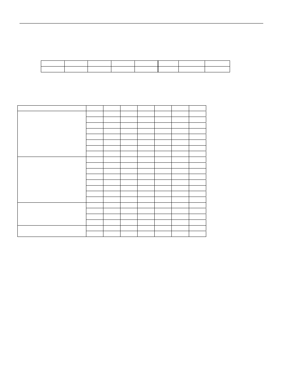
Register Name:
TLBC
Register Description:
Transmit Line Build-Out Control
Register Address:
7Dh
Bit
# 7 6 5 4 3 2 1 0
Name — AGCD GC5 GC4 GC3 GC2 GC1 GC0
Default
0 0 0 0 0 0 0 0
Bit 0–5/Gain Control Bits 0–5 (GC0–GC5). The GC0 through GC5 bits control the gain setting automatic gain control is
disabled. Use the tables below for setting the recommended values. The LB (line build-out) column refers to the value in the
L0–L2 bits in LIC1 (Line Interface Control 1) register.
NETWORK
MODE
LB GC5 GC4 GC3 GC2 GC1 GC0
0 1 0 0 1 1 0
1 0 1 1 0 1 1
2 0 1 1 0 1 0
3 1 0 0 0 0 0
4 1 0 0 1 1 1
5 1 0 0 1 1 1
6 0 1 0 0 1 1
T1, Impedance Match Off
7 1 1 1 1 1 1
0 0 1 1 1 1 0
1 0 1 0 1 0 1
2 0 1 0 1 0 1
3 0 1 1 0 1 0
4 1 0 0 0 1 0
5 1 0 0 0 0 0
6 0 0 1 1 0 0
T1, Impedance Match On
7 1 1 1 1 1 1
0 1 0 0 0 0 1
1 1 0 0 0 0 1
4 1 0 1 0 1 0
E1, Impedance Match Off
5 1 0 1 0 0 0
1 0 1 1 0 1 0
E1, Impedance Match On
2 0 1 1 0 1 0
Bit 6/Automatic Gain Control Disable (AGCD).
0 = use Transmit AGC, TLBC bits 0–5 are “don’t care”
1 = do not use Transmit AGC, TLBC bits 0–5 set nominal level
Bit 7/Unused, must be set to zero for proper operation.