Liu operation, Liu receiver, 1 liu o – Rainbow Electronics DS21458 User Manual
Page 159: Peration, 2 liu r, Eceiver, Figure 25-2. basic unbalanced network connections, Figure 25-2, Show basic balan, 1 liu operation
DS21455/DS21458 Quad T1/E1/J1 Transceivers
159 of 270
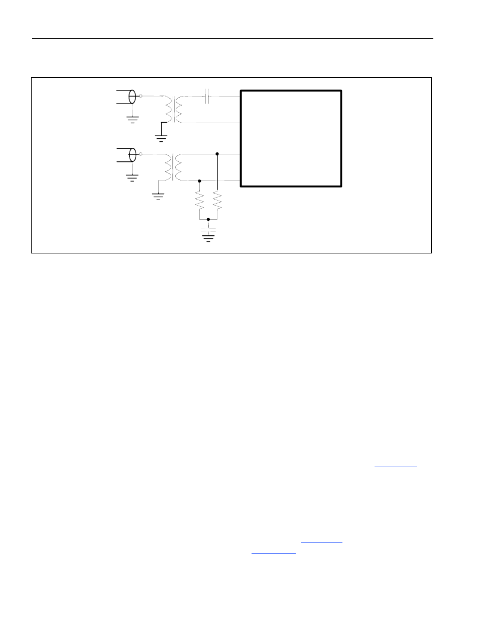
Figure 25-2. Basic Unbalanced Network Connections
25.1 LIU Operation
The analog AMI/HDB3 waveform off of the E1 line or the AMI/B8ZS waveform off of the T1 line is
transformer coupled into the RTIP and RRING pins of the DS21455/DS21458. The user has the option to
use internal termination, software selectable for 75Ω/100Ω/120Ω applications, or external termination.
The LIU recovers clock and data from the analog signal and passes it through the jitter attenuation MUX
outputting the received line clock at RCLKO and bipolar or NRZ data at RPOSO and RNEGO. The
DS21455/DS21458 contain an active filter that reconstructs the analog received signal for the nonlinear
losses that occur in transmission. The receive circuitry also is configurable for various monitor
applications. The device has a usable receive sensitivity of 0dB to -43dB for E1 and 0dB to -36dB for T1,
which allows the device to operate on 0.63mm (22AWG) cables up to 2.5km (E1) and 6k feet (T1) in
length. Data input at TPOSI and TNEGI is sent via the jitter attenuation MUX to the wave shaping
circuitry and line driver. The DS21455/DS21458 will drive the E1 or T1 line from the TTIP and TRING
pins via a coupling transformer. The line driver can handle both CEPT 30/ISDN-PRI lines for E1 and
long-haul (CSU) or short-haul (DSX-1) lines for T1.
25.2 LIU Receiver
The DS21455/DS21458 contain a digital clock recovery system. The device couples to the receive E1 or
T1 twisted pair (or coaxial cable in 75Ω E1 applications) via a 1:1 transformer. See
transformer details. The DS21455/DS21458 have the option of using software-selectable termination
requiring only a single, fixed pair of termination resistors.
The DS21455/DS21458’s LIU is designed to be fully software selectable for E1 and T1 without the need
to change any external resistors for the receive-side. The receive-side will allow the user to configure the
device for 75Ω, 100Ω, or 120Ω receive termination by setting the RT1 (LIC4.1) and RT0 (LIC4.0) bits.
When using the internal termination feature, the resistors labeled R in
should be 60Ω each. If
external termination is required, the resistors labeled R in
will need to be 37.5Ω, 50Ω, or 60Ω
each, depending on the line impedance.
TTIP
TRING
RTIP
RRING
DS21455
/
DS21458
Tx
Rx
0.047
mF
60
W*
60
W*
0.01
mF
*USE 60
W WHEN USING INTERNAL TERMINATION FEATURE.