Audio swap input matrix, Introduction – EVS IPDirector Version 5.8 - July 2010 Part 7 User's Manual User Manual
Page 207
Issue 5.8.B
IPDirector V.5.8 – User Manual – Part 7: Editing - IPEdit
EVS Broadcast Equipment - July 2010
194
3.
To define a GPI on the mark OUT point, perform the operations described in
step 2 for the Mark OUT GPI fields.
4.
Click Apply to save the Replace settings.
When the mark IN and mark OUT for the replace function are placed on the
timeline, the Replace GPIs are displayed on the Timecode bar as a green marker
for the mark IN GPI and a red marker for the mark OUT GPI. The GPI number is
mentioned on the marker and the marker position takes the offset into account:
Note
When you define a GPI for the mark IN and for the mark OUT points of
the Replace function, you need to define compatible GPI types, for
example a ‘level high’ GPI for the mark IN GPI and a ‘level low’ GPI for
the mark OUT GPI. The application will not prevent you from defining
incompatible types.
A
UDIO
S
WAP
I
NPUT
M
ATRIX
Introduction
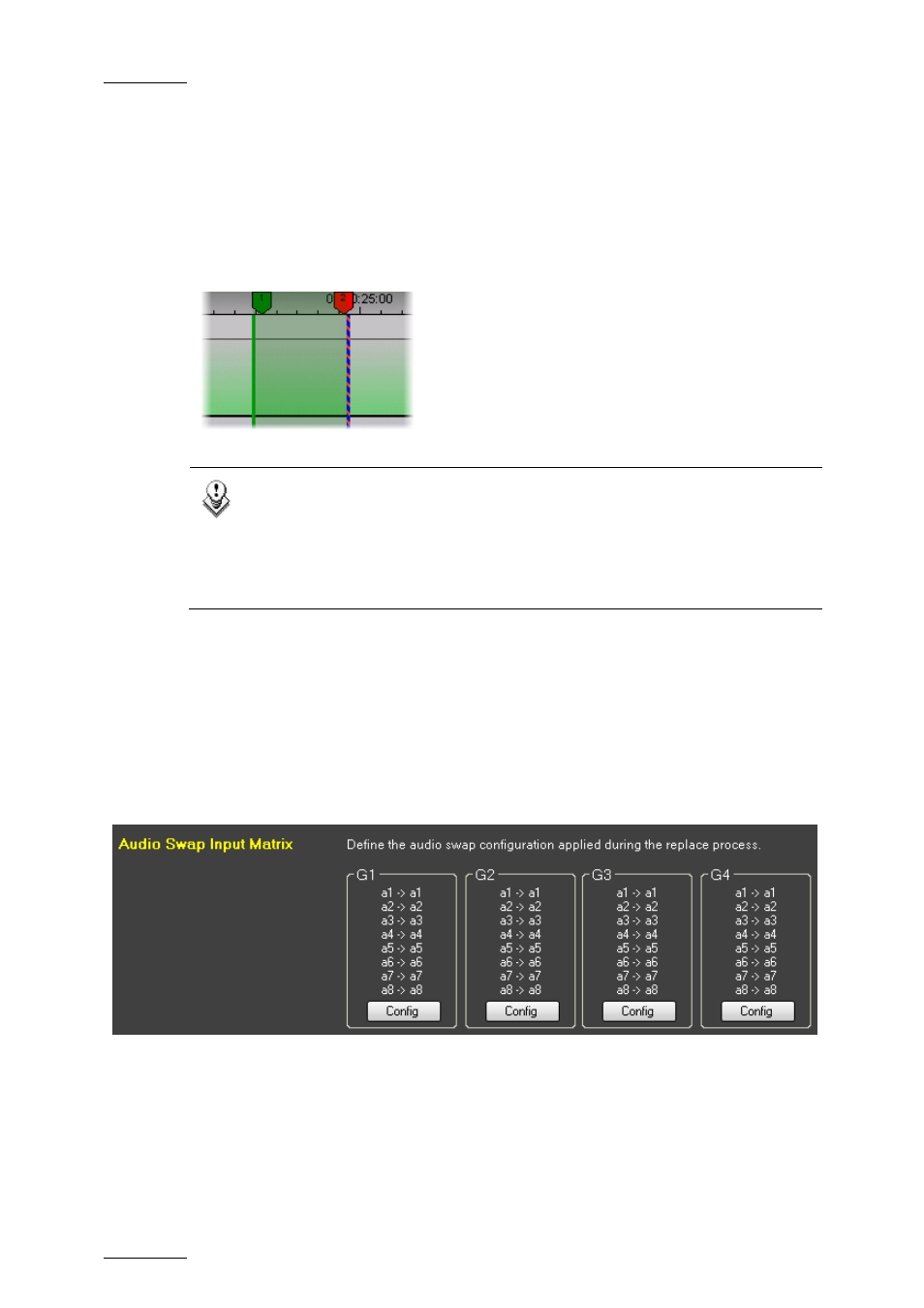
When you use the Replace function, the current track selection in the timeline
determines which track will be replaced.
If you want to route the result of the external mixing to a track other than the
original one, you can use the audio channel input matrix to configure how the
audio channels should be routed in the Replace process.
You need to click the Config. button corresponding to the requested track to open
the Audio Channel Input Matrix for this track: